Other Parts Discussed in Thread: TPS92692
I'm trying to figure out how to measure the Bode plot of a design that uses a component like the TPS92692. This application note is super helpful in identifying to correct location for small signal injection: https://www.ti.com/lit/an/snva364a/snva364a.pdf?ts=1673634833185
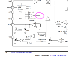
I hadn't thought of using a voltage follower for a system that doesn't have a clear location in the feedback loop that is low impedance on one side and high impedance on the other. But...what about a design that uses a device that has a differential feedback like the TPS92692. I feel like the only location that would fit the bill for high impedance on one side and low impedance on the other in the feedback path is after the internal current amplifier: .
.
Does this mean that you can't actually measure the transfer function and analyze the bode plot of an application that uses the TPS92692?

