This thread has been locked.

If you have a related question, please click the "Ask a related question" button in the top right corner. The newly created question will be automatically linked to this question.

BQ40Z80EVM-020: Controlling the LEDs and the LED Display Button

Part Number: BQ40Z80EVM-020
Other Parts Discussed in Thread: BQ40Z80,

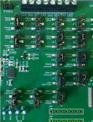
I am using a BQ40Z80EVM-020 and trying to control the LEDs provided on board. I have managed to make the LEDs work while the module is in charging mode, however the LEDs don't work while the device is in idle mode or while discharging. I have tried pressing the LED Display button for 4 seconds, but the LEDs still won't work. I have read the EVM's Datasheet and the Technical Reference Manual for the BQ40Z80, but haven't been able to figure out the LED working.

I presume I am doing some settings incorrectly. If anyone can help me figure out the settings, it would be a great help.

Thanks.

  • Hello Bhavil,

    Can you send a picture of your EVM jumper connections and a description of the jumpers you configured? Also a .gg file would be helpful so I can check the firmware is setup correctly.

    Sincerely,

    Wyatt Keller

  • Hi Wyatt,

    Below are the pictures of my Jumper connections, and the pin configuration which I have done according to the jumpers.

    Pin 12 - TS3 ([MFP12_SEL0][MFP12_SEL1][MFP12_SEL2] = 001 )
    Pin 13- TS4([MFP13_SEL0][MFP13_SEL1][MFP13_SEL2] = 001 )
    Pin 15- GPIO([MFP15_SEL0][MFP15_SEL1] = 10)
    Pin 16- GPIO([MFP16_SEL0][MFP16_SEL1] = 10)
    Pin 17 DISP (MFP17_SEL0][MFP17_SEL1][MFP17_SEL2] = 010 )

    Pin 20,21,22- LED ([MFP20_SEL0][MFP20_SEL1][MFP20_SEL2] = 000 )

    Here is the link to GG FILE.

    I also noticed that the voltage across TP5(DISP test point) and GND TP is pretty low (.155 V). Would that be the issue?

  • Hello Bhavil,

    Thank you for the additional data.

    I will need some time to review your configuration, I will respond by the end of this week at the latest.

    Sincerely,

    Wyatt Keller

  • Hello Bhavil,

    I reviewed all your settings and everything seems correct. Can you double check there is no CUV event occurring during your testing, and are you able to test with a different pin configured for the DISP functionality? I want to confirm if it is related to the pin or the actual FW functionality.

    Sincerely,

    Wyatt Keller

  • Hello Wyatt,

    No, I don't seem to have any CUV flags raised. I did try it with Pin 15 and Pin 13 in the past and tried it again this morning but the results are still the same. Although, when I changed the jumpers to change Pin 17 from DISP to GPIO and Pin 15 from GPIO to DISP, without changing the registers, I thought to try and press the LED Display button just to check. To my surprise, all 6 LEDs lit up for a couple of seconds and then LED D3 stayed on for a couple of seconds. My SOC at this point in time was 98%.

    After this, I changed the registers to proper values for Pin 15 and 17, but the LEDs won't work. I was not able to replicate the same after I changed the registers back too.

  • On a different note, I have prepared a schematic for BQ40z80 and would like a Schematic review, but I do not want to post it online. Is there any way, I can send it to you directly?

  • Hello Bhavil,

    I will try to setup and do some testing myself, but I will need a few days to test this, due to travel I may not be able to confirm until early next week. Can you also share the SREC file in the meantime so I can fully replicate your settings.

    You can send me a friend request on E2E and we can talk through private messege.

    Sincerely,

    Wyatt Keller

  • Hi Wyatt,

    You can download the SREC file from here.

  • Hello Bhavil,

    Thank you, I will try to test as soon as I can.

    Sincerely,

    Wyatt Keller

  • Hello Bhavil,

    Wyatt is out of office and will respond when he is back

  • Hello Bhavil,

    I was able to re-create your issue and I believe it's caused because the firmware is not enabling a pull-up on the pin when DISP functionality is selected. I tried using pin 15 as GPIO and was able to get it working without any issues (make sure you reset the gauge when you change the pin configuration to make sure it is updated, also LED_EN must be 1)

    I also see pin 17 is not pulled high, so it can't have a transition unless you pull it high, so I used pin 15 as GPIO and set it high and had pin 17 configured as the DISP pin, in this case it still works and the LEDs display the proper SOC. If you need to use pin 17 you will need some kind of pull-up on this pin. Pin 15 should work with no issues (it did on my side). I will report this to the FW team.

    Sorry for the delay, it took a little extra time since I believe the SREC shared was the default config instead of the golden image, once that was figured out I was able to confirm the behavior.

    Sincerely,

    Wyatt Keller

  • Thanks for the reply Wyatt,

    I was Out of Office for the past couple of weeks. I will try using both pins 15 and 17 and will get back to you.

  • Hi Wyatt,
    I tried using pin 15 as DISP and although i got a potential around 4.5V between the DISP test point and GND, the button still would not work. Is it possible I am missing some changes that I need to do under the LED Configuration section?

  • Hello Bhavil,

    I would double check your pin mapping as well on the EVM with the jumpers. I was able to get it functioning with the other pins.

    Sincerely,

    Wyatt Keller

  • Hi Wyatt,

    I started from scratch by doing the pin mapping and the pin configurations from the ground up but to no help. There is one thing that's confusing me. I am referencing both the Technical Reference Manual of BQ40Z80 and the User Guide for the BQ40Z80EVM. They both are showing some conflicting pin configurations. See the examples below

    If you see the pin configuration in the image below from the BQ40Z80-EVM User Guide, which suggests that to have Pin 17 as GPIO, the pin configuration should be [MFP17_SEL2:MFP17_SEL0]=100, which to me means MFP17_SEL2 should be 1 while the rest of the 2 should be zero.

    However, if I see this in the TRM for BQ40Z80, it suggests that to get Pin 17 to work as a GPIO, the pin configuration should be "Settings: Pin Configuration[MFP17_SEL0][MFP17_SEL1][MFP17_SEL2] = 100" which means that MFP17_SEL0 should be 1 and the other two be zero.

    Can you check this for me, please?

  • Hi Wyatt,

    Turns out I was using the TRM, whereas I should have been using the User guide, the button is working flawlessly now. Thank you for your support.