This thread has been locked.

If you have a related question, please click the "Ask a related question" button in the top right corner. The newly created question will be automatically linked to this question.

LM2576: Failure problem of LM2576D2T-ADJR

Part Number: LM2576

Hello E2E Experts,

Currently, we are facing the failure of  LM2576D2T-ADJR 

Different power supplies are generated with the help of this part. 5v,15v,12v,_15v,24v. We are facing failure in each type of power supply. 

The load on each regulator is very less. <1Amp

Input voltage is 37 VDC max.

The output is higher in most cases.

Then stops suddenly working. Below is the additional information:

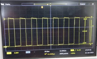
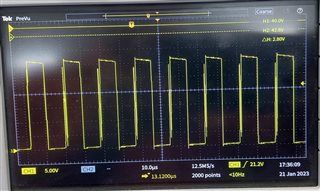
1. The regulator works fine for some time/some weeks. As we are using an adjustable regulator part no REGULATORS VOLTAGE SWITCHING 3A STEP-DOWN VLTG REG [PART NOLM2576T-ADJ/NOPB]. The failure comes from the machines installed in the field.

 When it fails

  • The regulator heats up and gives smoke.
  • The output of the regulator is high.
  • Sometimes there is no output.

1070.Design Files (2).zip

Kindly suggest how to prevent the failure of the regulator. 

Regards,

CSC
  • Hello

    1. Which regulators are experiencing difficulty ??, U1, U2, etc. ??

    2. It sounds like either a voltage spike on the input or a thermal problem.

    3. You PCB layout is not optimal.  You should be using ground planes for both the through hole and SMD applications.  It is best to follow the PCB layout in the data sheet

    The most critical area is the connection between the input capacitor ground, the diode ground and the device ground.  These should be as short and wide as possible.

    4. You may need more copper area for a heatsink for the SMD device and an external heat sink for the through hole device.

    5. Double check your designs with the Webench Designer tool for this device.

    6. Can you show us the switching waveform for normal operation.

    7. Make sure that no unexpected voltage spikes appear on the input of the regulator.  You may need some transient suppression on the input.

    Thanks

  • Hello Frank,

    Good day.

    Currently we are using 100µH 3A inductors for all the power supplies. The current rating is <1.5A for all the power supplies. The schematic of Power supply card was shared with you. Is the value of Inductors we are using enough or needs to change?

    Aditionally, please find switching waveform for +15V output supply below.

    Regards,

    CSC

  • Hello

    I think that 100uH is OK.  Also, be sure that your diode is correct based on the data sheet and/or

    Webench Designer.

    Thanks

  • Hello

    I will close this post due to inactivity.

    Thanks