A related question is a question created from another question. When the related question is created, it will be automatically linked to the original question.
If you have a related question, please click the "Ask a related question" button in the top right corner. The newly created question will be automatically linked to this question.
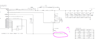
What you highlighted in you SCH above need to be connected ground connection of the remote sensing signal. The recommended VSNS– operating range as referred to AGND pin to be within is –50 mV to +50 mV.
Here is our recommendation for remote sense connections:
Connected the FB voltage divider resistors to the remote location, this will allow sensing to the output voltage at a remote location.
The connections from the FB voltage divider resistors to the remote location must be a pair of PCB traces with at least 12-mil trace width,
Implement Kelvin sensing across a high bypass capacitor of 0.1 μF or higher.
The ground connection of the remote sensing signal must be connected to the VSNS– pin.
The VOUT connection of the remote sensing signal must be connected to the feedback resistor divider with the lower feedback resistor, and should be terminated at VSNS– pin.
Please use Webench to create an initial design based on your conditions
For remote sensing, connect to it to GND. Use PCB traces with at least 12-mil trace width, and must implement Kelvin sensing and should be within +/-50mV with respect to AGND.