This thread has been locked.

If you have a related question, please click the "Ask a related question" button in the top right corner. The newly created question will be automatically linked to this question.

LM74502-Q1: Gate to SRC impedance reduced to 10 ohms

Part Number: LM74502-Q1


Hi Team,

Can you please help answer the inquiry below?

When using LM74502-Q1 to drive the back-to-back MOSFET, after a period of time, use a multimeter to measure the resistance of the gate pin to the SRC pin, and it is found that the resistance decreases to 10 ohms, but the chip can drive the mosfet normally.

Can you help me understand why? thank you.

Regards,

Chase

  • Hi Chase,

    Please share your circuit schematics and the test condition at which you are measuring the GATE-SRC resistance.

    Is the EN/UVLO pulled low when you are measuring the GATE-SRC resistance ?

  • Hi Praveen,

    Thank you for your timely reply.

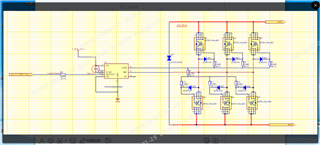
    The circuit schematic  is as follows.

    We measure the  GATE-SRC resistance when the power is off,so the EN/UVLO pin is floating.

  • Hi Praveen,

    Further analysis showed that the bootstrapping capacitor had a residual voltage after power failure, and the GATE-SRC impedance tested at this time was only a few ohms. The impedance between GATE and SRC is normal after the residual voltage of bootstrap capacitor is discharged. Based on this phenomenon, we would like to know the internal hardware framework of LM74502-Q1 to evaluate whether this situation poses risks to the design. At the same time, I hope TI can help to evaluate whether there are risks.

    thanks

  • Hi,

    When the input  power supply is absent there will be a passive pull down between GATE-SRC pins so as to keep the FET OFF. 

    Can you share the measurement results of the impedance measured across the GATE-SRC pins vs the charge pump cap voltage  measured at different instances. 

  • Hi,

    After the chip is powered off, the residual capacitance voltage of the charge pump is 1.7V, and the impedance of GATE-SRC is 2 ohms. The residual charge pump voltage is lowered to 0.3V, where the impedance of GATE-SRC is 78K ohm

  • Hi, Thanks for the information. Let me get back to you with an explanation for this behavior. 

  • Looking forward to your reply. And  I'd like to know the internal hardware architecture of this chip if possible。

  • Hi,

    Your observations are expected. Using the power  from the charge pump capacitor the 2Ω active pull down between GATE-SRC remains functional and then when the charge pump capacitor discharges the active circuit can no longer provide low-impedance between GATE-SRC and hence you will just measure the passive resistance between the GATE-SRC.

    Unfortunately we will not be able to reveal more details on the gate architecture beyond what is showed in the functional block diagram of the datasheet.

    Regards,

    Praveen