This thread has been locked.

If you have a related question, please click the "Ask a related question" button in the top right corner. The newly created question will be automatically linked to this question.

UCD90320: UCD90320 discussion on PMBus access. - abnormal driving low on SDA signal

Part Number: UCD90320


It is found when our master (MCP2221) communicates with UCD90320 via PMBus, sometimes the PMBus was hang as the SDA kept low. Not sure what happened on this.

Could you please check the below experiment data and see whether there is any method to access the DPM status or analyzing the issue? Thanks.

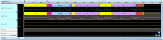
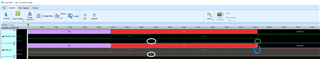
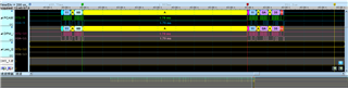
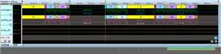
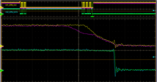
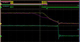
1. As the issue happened, the DPM_I2C bus hang, and further the DPM shows strange behavior. (the output pins seem not working as the designed logic, such as the lower channel on the LA waveform)

2. It can be seen the i2c not getting a STOP on the interface.

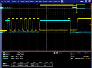
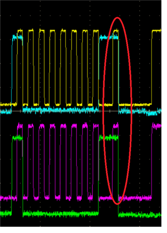
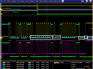
3. As the green (SDA on master side) and blue (SDA on DPM side) signal, there is PCA9546 between the master and DPM side. The DPM seems driving low earlier. Meanwhile, when the SDA trace broken out by the wire, the SDA on DPM side is still low.

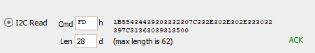
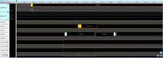
4. pleaes refer to the attached file for the traffic transaction between MCP2221 and UCD. (open with Acute LA tool.)

LogLA_230118_110616_With DPM I2C&Scope.zip

  • Hi

    1. does you host support clock stretching? This is very critical. Without clock stretching, the communication will not be reliable 

    2. what 's firmware version running on the device? please use block read to read command 0xFD.

    Regards

    Yihe

  • Thank you for the prompt feedback. 

    1. the MCP2221 support the clock stretching on the traffic. is there any specific clock stretch requirement (e.g. how long of the clock stretching can wait? and etc.) for the master communicating with the UCD90320?

    2. for the UCD90320, we ever used UCD90320ZWSR and UCD90320ZWST. is the FW embedded in the PN information? or we can always read it out from the 0xFD in real chip?

  • HI

    under what kind of transaction(write or read), this occurred.

     I need see a complete transaction waveform with zoom in to see each clock bit.  The host shall not only support clock stretching up to 35ms and also need to handle timeout case.

    The FW revision is part of 0xFD command from IC.

    There are a few command protocols that UCD does not support and host shall avoid.

    1. send a device address with either W or R bit + STOP.

    2. read data from UCD use STOP + START instead of RESTART

    Regards

    Yihe

  • Thank you Yihe,

    Due to the holidays, I paused to response this for long. Please check some below and let's resume the discussion while I can use the equipment for the data collection for this issue.

    1. What we got from the DPM with 0xFD is 00 91. Is the FW version new and stable enough?

    2. The transaction details are included in the zip file in the beginning of this discussion thread. there is also the rough snapshot on the following.

    (kindly refer to the following link to download the tool of MSO3000 series for decode the MSW file inside the zip file.)

    https://www.acute.com.tw/logic-analyzer-en/support/download/software

    3. In the above information, do you think we hit some condition which should be avoided for UCD?

    4. In our observation, the ACK period is pretty long from the MASTER device (MCP2221) comparing with the other transaction waveform. Is this a limitation of UCD?

  • HI

    The returning of 0xFD is wrong and obviously, there is some issue here.

    If you can not get 0xFD working, it is not surprised that you have issues elsewhere. Let's focus on the 0xFD.

    When there are so many 0xFF present, it means that none drives the SDA so that it is high by default. 

    Please use scope(not the sniffer or digital analyzer tool) to capture the waveform when performing 0xFD read.

    Here is what expected returned from the device

    Regards

    Yihe

  • hi Yihe,

    It was my bad on accessing the 0xFD. Please refer to the following snapshot on the feedbacking value; and let me know if there is any. Thanks.

  • Hi

    Via reviewing your capture, we did release the SDA on the rising edge of the SCL but somehow on the PCA side, it did not see this so the SDA is always low.

    What's pull-up resistor used here?

    Regards

    Yihe

  • Hi Yihe,

    Thank you~ You can see the waveform in the normal condition is the transaction will have a STOP token and then release the bus.

    and the following waveform is the condition with failure. The SDA is driven low and the STOP token cannot be issued. Further the bus is hanged.

    From the above cases, it shows the difference on the final NACK token. The SDA was driven low right after the SCL driven low in the failure case. Then the master cannot drive out the STOP token.

    In the normal case, the SDA will still be kept high after the SCL released to high to create a STOP token.

    That's what we'd like to focus on and wish TI can give us some direction on analyzing the status inside the UCD.

    The pull up resister is using 2k ohm on both of SDA and SCL. Also the following shows the topology.

  • Hi 

    From the waveform, the DPM I2C_SDA was high but PCA side it is low. 

    You need have a scope to capture all these. The tool capture you have did not have the details to show.

    Regards

    Yihe

  • Hi YiHe,

    Thank you. I would circle the SDA lines as the following. Kindly refer.

    You can refer to the waveform on the final byte transaction. I cannot see abnormal signal before hang.

    For the timing spec. review, we actual have some conditions which may not induce the bus hang. Therefore we compare their difference on the timing. you can see the tBUF, and tLOW have great different between hang and non-hang condition. Could you please take a review on whether this is the limitation on the UCD's PMBus?

    Symbol

    Parameter

    Min

    Max

    Units

     hang condition

     condition without hang

    fSMB

    SMBus operating frequency

    10

    100

    KHz

    97K

    100K

    tBUF 

    Bus free time between Stop and Start condition

    4.7

    µs

    204.58 mS

    315.75 uS

    tHD:STA

    Hold time after (repeated) Start condition. After this period, the first clock is generated.

    4

    µs

    5us

    5.15uS

    tSU:STA

    Repeated Start condition setup time

    4.7

    µs

    5.7us

    5.55uS

    tSU:STO

    Stop condition setup time

    4

    µs

    5.52uS( Typical)

    5.52uS

    tHD:DAT

     Data hold time

    300

    ns

    580nS

    395nS

    tSU:DAT 

    Data setup time

    250

    ns

    4.485 uS

    4.5uS

    tTIMEOUT

    Detect clock low timeout

    25

    35

    ms


    tLOW 

    Clock low period

    4.7

    us

    4.9 us

    4.8 us

    tHIGH

    Clock high period

    4

    50

    us

    5.5uS

    5.2uS

    tLOW:SEXT

    Cumulative clock low extend time (slave device)

    25

    ms

    2.5mS( Typical)

    801uS

    TLOW: MEXT 

    Cumulative clock low extend time (master device)  

    10

    ms

    1.8mS

    361.5uS


  • addendum for the timing difference:

    Master- MCP2221 (hang condition in previous table). The transaction waveform always has longer ACK to next Sr period. It induces longer tLOW (SEXT and also MEXT)

    Master- MCP2221 (hang condition in previous table). The bus is freed for longer time period, between any of 2 transactions. It induces longer tBUF.

    another Master. (non-hang condition in previous table). The transaction waveform always has shorter ACK to next Sr period (comparing with the MCP2221 case)

    another Master. (non-hang condition in previous table). The transaction waveform always has shorter bus free period. (comparing with the MCP2221 case)

  • Hi

    Thank you for the waveform.

    The bus free time shall not be matter here since there is no transaction. But the clock low before RESTART 1.8ms(TLOW:MNEXT) is quite long. Do you know why it take so long? is this software based I2C master? 

    Even so, i am not aware any issues.

    The capture showed that the hung is on read. 

    Could you help capture scope the following:

    1. a good read - need a complete transaction+ details of each bits  

    2. the read with hang - need a complete transaction+ details of each bits

    I want to compare

    Regards

    Yihe

  • Thanks Yihe,

    the following 2 waveforms is same address / command and same read out value from the MCP2221.

    Master- MCP2221- write 8C to 0x11

    Master- MCP2221- read 0x11

    After the following transaction, the bus hang as SDA kept low.

    Master- MCP2221- write 8C to 0x11

    Master- MCP2221- read 0x11. 

  • Hi

    Thank you for the capturing. you can see the NACK is quite different between two different case.

    The good one is very clear(SDA high on the ACK clock bit)  but the bad one the falling edge of the SDA is kind of inside the CLK cycle(pink and green). Why does Master pull low the SDA so quickly?

    Regards

    Yihe

  • my observation is as the following:

    the white frame seems driven by DEV. and pink frame seems driven by Master. 

    as this is the read command and getting 00 back, than the Master drove out the ACK. 

    in the final few segments of this waveform, as my marked frames, it seems the low is driven by DEV, Master and then DEV again.

    my reading is the voltage level is slightly different on the low. The Master will drive more lower, and the DEV drives a little higher.

    also, in the following waveform captured in originally. You can see the DEV drive the SDA from the branch of the SMBus firstly and then the Master side was affected.