This thread has been locked.

If you have a related question, please click the "Ask a related question" button in the top right corner. The newly created question will be automatically linked to this question.

BQ40Z80: Diode connection between BAT and VCC pin

Part Number: BQ40Z80

Dear Support,

i would like to ask you something else related to this specific case scenario. You said that i need to connect BAT pin to VCC pin through the diode in order to simulate the presence of the body diode of MOS (in the typical configuration). How can i connect this diode? I put in the table below two possible cases:

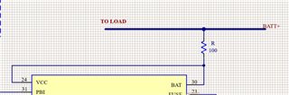
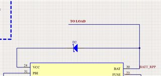
-CASE1: i connect the diode between BAT and VCC but the discharge current flows through another path (in my case i can have up to 5 A), so i think the diode can be realtive small and i can save space

-CASE2: i connect the diode between BAT and VCC on the same path of discharge current and in my case i need to choose the diode accordingly to this constraint
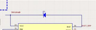
CASE 1 CASE 2

What is the right choice? 

Thank you in advance,

Giorgio

  • Hello Giorgio,

    Do you have any high side protection FETs? If you do the VCC connection should be on the system side so if the batteries become very low the gauge can be woken up from a charger still.

    In that case I would connect your VCC to the system side with a 100 ohm resistor. If you don't have high side then I would connect VCC to the same node as the BAT pin after the diode. The diode is there to prevent a over-charge condition to the batteries if there is an internal short of the gauge.

    How are you planning to connect the PACK pin without protections?

    Sincerely,

    Wyatt Keller

  • Hi Wyatt,

    thanks for your answer. 

    I add some more info that may help you: am using a battery pack that has all the protections, so BQ40Z80 is used only for gauging and balancing and DSG and CHG pins are left floting, as you already suggested in the related question to this topic. 

    How can i connect VCC pin to BAT pin? 

  • Hello Giorgio,

    Ahh I see, so if the battery protections are triggered the gauge will lose power.

    I would directly connect VCC and BAT pin in that case, both would be after the diode.

    Sincerely,

    Wyatt Keller

  • Hi Wyatt,

    just to be clear, in THIS topic, you suggested to my colleague to connect BAT to VCC throigh a diode: which solution is the best?

    If i can direcly connect VCC and BAT, should i decouple the power line to the load with a 100 Ohm resistor? (as reported in the image below. The thicker line is the path where high current passes through). 

  • Hello Giorgio,

    I needed to understand your system better to give a more accurate suggestion, the main purpose of the diode and resistor is to prevent a direct path from the system side to the top of the battery stack if there was an internal short in the gauge. It's for additional protection.

    Essentially these are suggestions, only using a resistor is also a valid solution to help prevent a short condition, a diode would be preferred since it could stop any current flow.

    Sincerely,

    Wyatt Keller

  • Hi Wyatt,

    i uploaded a schematic in which you can see how my system looks like: as i said, my battery is 3S and each cell has its own protection already embedded.

    Gauge_config.pdf

    I hope that now my system is clear and i hope that you can suggest me the best solution for the VCC and BAT pins.

    Thanks a lot again.

    Giorgio

  • Hello Giorgio,

    Since you have protection on the batteries already the amount of protection you need is not significant since batteries can't be over charged or shorted to be the gauge. A resistor to the pins should be fine as you have in your post from yesterday(100ohm).

    Sincerely,

    Wyatt Keller

  • Hi Wyatt,

    thank you so much for your support.

    Have a nice day!

    BR

    Giorgio