This thread has been locked.

If you have a related question, please click the "Ask a related question" button in the top right corner. The newly created question will be automatically linked to this question.

UCC28C45: Flyback converter with wide range input

Part Number: UCC28C45


Hello,

I have a below requirement.

Input voltage: All range battery input i.e. 14.4V to 154V input

Output Voltage: 2.8VDC

Output Current: 0.1A to 2.5A (can switch immediately)= Wattage of ~9W

Topology: PSR, Flyback

Ripple of +/-50mV max.

Size: 25mm*100mm

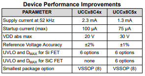
With the above requirement i found UCC28C45 to be good match.

Do you have any better suggestion? As this is critical project to replace the current solar cell with battery supply.

  • Hello Deepak,

    The UCC28C45 can certainly work.  Are you aware of TI's Webench Design Tool?  I used TI's Webench tool to create a preliminary isolated design for you with 14.4-154Vin, 3.3Vo, 2.5A, 100kHz (see PDF).  Webench would not provide a design for output voltage below 3.3V but it can be modified for 2.8V.

    WBDesign62.pdf

    You should also consider TI's new revision of this controller, the UCC28C55.  It is a direct replacement with higher Vin rating, improved reference tolerance, and lower startup/operating currents.

    Regards,

    Eric

  • Thanks Eric for support.

    Now i have 2 more questions:

    1. The tool suggests using a opto based feedback. As per my understanding, instead we can also do a Primary side voltage regulation with auxiliary winding (used for IC's Vdd). Can you forsee any issues here?

    2. Considering the current switching of 0.1 to 2.5A for 2.8Vdc and ripple limitation to +-50mV even during transition, would it be a good solution to have 12V output and later use a buck for stable 2.8Vdc. What is your opinion? Is flyback alone suitable for such reuirement?

    Looking forward for valuable response.

    Regards,

    Deepak

  • Hi Deepak,

    1. For some reason Webench will not provide a non-isolated design/report for the UCC28C45.  TI has supported many designs with primary side regulation, so it's 100% possible.  Of course, PSR puts some emphasis on the design of the auxiliary winding to have good coupling and output regulation.

    2. I see you want to have a good transient response when the load steps from 0.1A to 2.5A. The bandwidth of the flyback may not be enough to maintain +/- 50mV with a very fast load increase/decrease.  If you can afford the cost, adding the buck is a very good idea.  I know the buck typically has higher loop bandwidth than a flyback.  To confirm, I would do some simulations of flyback alone, then flyback+buck.

    Eric

  • Hello again Deepak,

    50mV is only 1.8% of 2.8V.  The DC accuracy alone of a PSR flyback will be challenged to meet this specification.  I think you must add the buck for this level of accuracy.

    Eric

  • Thanks eric,

    To update the further progress and avoid any unforseen issues i request to have your personal email id

  • Hi Deepak,

    I sent you my TI email address.  TI's policy about E2E is to provide response within 24 hours, so that is the preferred route.

    Regards,

    Eric