This thread has been locked.

If you have a related question, please click the "Ask a related question" button in the top right corner. The newly created question will be automatically linked to this question.

BQ27426: Jump in SOC during battery discharge

Part Number: BQ27426
Other Parts Discussed in Thread: GPCCHEM, BQSTUDIO

Hi:

Information on the batteries used in our tests is as follows.

Cell/Pack Info
Cell/Pack Maker* BYD
Cell/Pack Model* LP113129
Design Capacity* 1230
Charge Voltage* Cell:4.40V
Cut Off Voltage* 3.3V
Cell chemistry Li-ion Battery

The Fs file provided by TI after the golden learning has been loaded.

Problem Phenomenon.

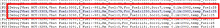
During discharge, there is a problem of SOC jump, please help to confirm what is the cause?

25℃ 0.2C discharge (12mAh per discharge, leave for 10 minutes), SOC 18% - 0%

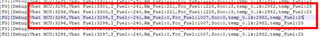
1A discharge at 25°C (12mAh per discharge, 10 minutes standing), SOC 10% - 1%

  • Hello Wang,

    I would check Load mode/load select settings first to make sure it matches the discharge rate.

  • Thank you for your support.

    When will it be confirmed?

    What is the method to check load mode/load select setting and discharge rate?

    Are there any other points of doubt?

    Could the RA meter be mismatched with the battery? How can I confirm the correctness of the RA table?

    Does the Chem Data data not match the battery? How can I confirm the correctness of Chem Data data?

  • Information about load mode/select is in the TRM www.ti.com/.../sluubb0.pdf, 7.4.2.3.4 Load Select, Load Mode. These settings control how the gauge predicts a discharge, which is the basis of the algorithm.

    About Ra and Chemistry: It's critical that you select a compatible chemistry. The bq27426 has three built in ChemIDs. You can use GPCCHEM https://www.ti.com/tool/GPCCHEM to check, if one of the built in ChemIDs is compatible (the report includes this information). Note that this report also identifies the best match ChemID, which is typically not a built in ChemID. It will list the max. DOD error for all built in ChemIDs.

    After you select the best ChemID from the built in ChemIDs and after configuring the gauge as per the Quick Start Guide (https://www.ti.com/lit/pdf/sluubn3), you must run a learning cycle (https://training.ti.com/how-perform-successful-learning-cycle-gauges) before the gauge will be accurate.

  • Thank you for your support.
    The FS files for Chem ID and godlen learning onwards have been provided by TI. When we loaded the Fs file and performed the discharge test, there was a SOC jump. So we would like to know.
    1. What is the reason for the SOC jump?
    2. How to solve the SOC jump phenomenon? Which register values need to be printed for analysis?
    3. How to confirm whether the Fs file matches the battery?
    4、How to confirm whether the chem id data matches with the battery?

  • Please describe exactly how you use the files that were provided by TI.

    #2: We need a register log file (time (in seconds), current, voltage, temperature, SOC, true remaining capacity, true full charge capacity), with a log interval of less than 5 seconds. This file must include the initial OCV measurement (it must be a relaxed cell) and it must show the SOC jump.

    #3, #4: You can check this with GPCCHEM www.ti.com/.../GPCCHEM, which will return a list of compatible ChemIDs.

  • TIDemo_TEMPS_01b_1A_jingtai_0129.log

    Thank you for your support.

    Attached is a log of a test using the TI EVM board, which showed a SOC jump of 24% - 0%.

    The configuration is as follows:

    ...

  • Additional configuration screenshots

  • One problem is that the system discharges the cell with pulses that last about 40-50 seconds. The gauge will not learn how to predict load with pulses that are that short. The Avg I Last Run from your screenshot is -49 [0.1Hr rate]. Therefore the gauge uses a predicted load of 1230mAh/-4.9h = -251mA. But your actual load is -998. Therefore Avg I Last Run (and Avg P Last Run) must be -12 [0.1Hr rate).

    Please also test this first with a constant current non-pulsed load before moving to a pulsed load. This ensures that the basic configuration is good.

  • Thank you for your support.
    We have modified the discharge test method for testing, which is to discharge at 0.2C for 540s and then stop for 10 minutes and cycle through. However, the test showed: 99%-1% normal, an abnormal jump to 6% at 1%, and then an abnormal jump from 5% to 0%. (Please check the log below.)
    Please check again if there are any other notes related to the discharge test so that we can check and confirm them as soon as possible.SOC_JUMP_LOG.txt

  • BTW, we see that the learning process is a constant current discharge, but we test with a 540s constant current discharge followed by a 10min rest cycle, would a constant current discharge gold learning, cover us in this testing method? Is there any other learning process needed?

  • The golden learning should be done with a constant current (between C/2 and C/5) so that the gauge can learn chemical capacity and cell resistance.

    If you want to test an actual use case, you must make sure that load prediction is configured correctly. See TRM https://www.ti.com/lit/ug/sluubb0/sluubb0.pdf, 7.4.2.3.4 Load Select, Load Mode

  • Thank you for your support.

    Our test scenarios are as follows.

    Scenario 1: 0.2C discharge, after the power is reduced by 1%, stop discharging, 10 minutes later again 0.2C discharge. Cycle until the battery power is 0%.

    Scenario 2: 1A discharge, after the power is reduced by 1%, stop discharging, and after 10 minutes, discharge 1A again. Cycle until the battery power is 0%.

    For the above test scenarios, there are the following questions.
    1, according to the 0.2C constant current charge/discharge execution of golden learning, whether it can cover?
    If not, what other operations need to be done?
    2. How should we configure Load Select/Mode?

  • #1: 0.2C is ok for a learning cycle.

    #2: You'd have to configure two different scenarios. The gauge won't "know" which one will happen so if you configured load select for scenario #1 (e.g. present average load), followed by #2, then the gauge will first use the average load from the previous discharge (#1) to predict capacity for scenario #1. It's more problematic, if you switch from 0.2C to 1C or vice versa during a discharge because the gauge will (by default) use the average load that it measured during the discharge so if the load suddenly changes, the gauge will take some time to adjust.

  • Thanks for the support.
    Is it then fair to assume that if the predicted current or power of the power meter is more accurate, the SOC can be calculated accurately and without jumps?
    Also, we see that the current SOC jump occurs at the discharge cut-off voltage, is it understood that there is an algorithm within the power meter that forces the SOC value to be set to 0% once the discharge reaches the cut-off voltage?

  • Yes. This is correct. By default, the gauge will adjust during a discharge based on current measurements but this isn't instantaneous. It will also use previous average load for the initial FCC and RM prediction.

    The gauge will force SOC to 0% if the cell voltage drops below Terminate Voltage for the required time during discharge. This will cause an SOC jump, in case the prediction was incorrect.

    An extreme example would be if you discharge with a light current, e.g. C/5 and close to end of discharge, the load increases to 3C, then the cell voltage will drop below Terminate Voltage because at the moment that the load changed that much, while there was still some capacity available (e.g. 5% SOC) for a C/5 load, there's absolutely no capacity left (for this cell state DOD) and a 3C load.

    You can configure the gauge conservatively. The most conservative approach would be to use a User Rate with the worst case. The gauge would intentionally underestimate capacity (because it uses the User Rate for the worst case load) so SOC would reach 0% early. Other, less aggressive methods would be to use a Reserve Capacity that can cover a worst case load spike close to end of discharge.

  • Thanks for your reply.
    If the 2 usage scenarios mentioned above are tested independently, could you provide the recommended load-related configuration?

  • I would configure it for an average load (default setting) and add a reserve capacity that covers the worst case pulsed load close to end of discharge. The reserve capacity should be close to the SOC jump that you observe in your tests (e.g. if it's a 4% jump, use 4% of Design Capacity and Design Energy for Reserve Capacity.

  • Thanks for your reply.

    What does "add a reserve capacity" mean? How do I need to operate it? What is the corresponding register value?

    Currently the value of SOC Jump is not fixed during our testing, how can we increase the reserve capacity in this case?

  • The gauge has a configuration parameter: "Gas Gauging","State","Reserve Cap-mAh","xxx","mAh"

    You can set this to a reasonable value that will cover the capacity loss for a sudden change in load, as in your application.

  • Thanks。

    1、We use the mode when load mode=1.
    What is the scenario when load mode=1, and what is the scenario when load mode=0. How to choose the appropriate load mode?

    2、How to determine the value of Reserve Cap-MmAh? Is there any guidance document?

  • A few additional questions:

    1. Is it normal for SOC jump to occur during discharge?
    Within what range of SOC jump can be considered as normal? (e.g. 2%-->0% or 10%--0%)

    2、Can the watchdog of FuelGauge be turned off? How to turn it off?

    3、What is the minimum interval period for reading data in Data memory under the premise of ensuring the normal operation of FuelGauge?

    4、What is the working principle of Gas Gauging->IT Cfg->TermV Valid t? [e.g. (1) Set to 2sec, after battery voltage <Terminate Voltage, delay 2sec, SOC set to 0%? (2) Set to 2sec, battery voltage ≤Terminate Voltage for 2sec continuously, SOC set to 0%?]

  • Dear Dominik Hartl

    Is it possible that we are having an online meeting and if so, hopefully we can contact and communicate the exact time by email.
    Thank you!
    The email address is: chengxiaobin@tricheer.com

  • Load mode: The gauge will either use a constant current or constant power during discharge simulations. This should be set to match the application. If the application draws more current (average) as cell voltage drops, load mode should be set to constant power (default).

    Reserve Cap: There is no guidance document because it is highly application specific. A cell's remaining capacity depends on the load so if the load may increase close to end of discharge, then the cell voltage may drop below terminate voltage because the new scenario means that there is no capacity left. If this is a possibility, you can choose a reserve capacity that the gauge will remove from its capacity prediction (in anticipation that there may be a sudden increase in load close to end of discharge).

    SOC Jumps: It's not normal and the gauge should be configured to prevent these jumps. That said, because capacity is a function of future load and temperature, which are not known 100% for sure when the gauge makes a capacity prediction, some predictions will be done with incorrect assumptions (load and temperature) and therefore it's not unusual to see some SOC jumps, especially if the gauge is configured to predict for a static discharge scenario, which doesn't match the application.

    Watchdog: This cannot be turned off.

    I don't understand the question about minimum interval period.

    TermV Valid t: Measured cell voltage during discharge must drop below Terminate Voltage for at least TermV Valid t before the gauge zeroes out RM and SOC.

  • Thanks。

    minimum interval period:Described in TRM"For readwrite standard command, a minimum of 2 seconds is required to get the result updated. For read-only standard commands, there is no waiting time required, but the host must not issue any standard command more than two times per second. Otherwise, the gauge could result in a reset issue due to the expiration of the watchdog timer".

    Is there a similar limitation for register reads in Data Memory? What is the minimum interval between two reads?

  • If the gauge is in config update mode, the limit does not apply because the gauge will not run discharge simulations.

  • Thanks for your reply.

    Sorry, my requirement may not be described clearly.

    1、To perform a read operation on Extended command, no config update mode is required. is the understanding correct?

    2、What is the minimum interval between read operations for a single command in the extended command of FuelGauge IC? What is the recommended value?

    3、What is the minimum interval between read operations for the standard command of FuelGauge IC? What is the recommended value?

  • Our current setting TermV Valid t is 120sec and there is no jump. Our understanding is: when the discharge starts, the battery voltage will become low (0.2C, voltage about 0.1V; 1A, 0.3V or so). 10% of SOC or less, without discharge, the battery voltage is about 3600+mV, when it starts to discharge continuously, it will cause the battery voltage to reach the set value of Terminal Voltage (3300mV). After changing from the default value to 120sec, during discharge, the battery voltage reaches Terminal Voltage and needs to be continuously below Terminal Voltage for 120 seconds before SOC becomes 0%, so there is no jump.

    Is the above understanding correct? What are the risks of such a modification?

  • Yes, this is correct. The risk of this modification is that the system will shut down, if the voltage drops so low.

  • Thanks for your reply.

    If the Term Valid t register is modified, will it have an impact on other functions of fuelguage (e.g. prediction of critical data such as SOC, RM, FCC, etc.)? Is it necessary to modify other registers simultaneously?

  • It won't affect predictions for SOC, RM and FCC but it will affect RM and SOC behavior close to end of discharge because the gauge will wait accordingly before zeroing out SOC and RM.

    This parameter can be changed by itself without having to change other parameters.

  • Please reply to the following questions with your help:

    1、To perform a read operation on Extended command, no config update mode is required. is the understanding correct?

    2、What is the minimum interval between read operations for a single command in the extended command of FuelGauge IC? What is the recommended value?

    3、What is the minimum interval between read operations for the standard command of FuelGauge IC? What is the recommended value?

  • #1: correct.

    #2: If the gauge is actively gauging (=i.e. not in config update mode), the official answer is no more than 2 commands (including extended) per second.

    #3: No more than 2 commands per second. The interval between commands isn't critical. The overall communications load is what must be controlled.

  • Thanks for you reply。

    #2 We need to read the data in Data memory periodically for checking whether the data is changed or not. For this scenario, can we follow the 1sec 1 register approach? For example: read subclass id 64, delay 1sec, read subclass id 80......

    #3 How to make sure the communication load is already full? Will the cyclic reading of commands at 1sec intervals cause the load to be full?
    We read multiple register values (chem id, current, voltage, RM, FCC, SOC, SOH, etc.) continuously at 1sec interval, will it cause the communication load to be too large? What is your recommended interval?

  • #2: Please do not read whole subclass during regular gauging. It's too much data load on the gauge.

    #3: There is no method to measure this. The gauge wasn't designed for configuration to be queried during gauging so what you are doing will cause problems. Please don't read the configuration during gauging. This can be done in config update mode. You can still read a few parameters during gauging but the more you read, the higher the likelihood of a WDT reset becomes.

  • Thanks for you reply

    Since there is no guarantee that the data in Externed Commands will not be changed under various disturbances, we need to check the readback periodically.
    Can we guarantee that the data in Data memory will not change in SEALED state?

    #2 If we read the data in Data memory according to 10sec cycle, can we reduce the Fuelgauge load rate? For example: read SubclassID64, delay 10sec, read SubclassID 80, delay 10sec, Read SubclassID 82.... Loop through.

    #3 Using battery management studio, we can set the log read to 1sec, so we think we can read the data of multiple standard instructions in 1sec, and the rate of i2c is 100KHz, which is perfectly suitable for data transfer. Is this understanding correct?
    Because the application needs to periodically read the data of the standard instructions (chem id, current, voltage, RM, FCC, SOC, SOH, etc.), if each standard instruction is delayed by 1 second, it will not be able to obtain the exact data at the same time.
    What is the maximum number of standard instructions that TI believes can be read in 1sec to ensure Fuelgauge is operating properly?

  • The data will not change in sealed state.

    #2: Yes, this will work.

    #3: There's a possibilty that a 1s period selected in bqStudio will cause a WDT reset if bqStudio reads several registers. Note that the WDT reset isn't guaranteed to happen. It will only happen, if the communication exceeds 2 commands per second *and* the gauge runs a long discharge simulation. These two events are not synchronized and the 2 commands per second limit is a guarantee that it will not cause a WDT reset. So if bqStudio issues more than 2 commands per second, then it will work fine for possibly a long time until, by chance, the events align causing a reset.

  • Thanks for you reply.

    #3 Only during discharge, communication more than 1 second 2 times, there is a probability that WDT will occur. charging or relax, communication more than 1 second 2 times, will not occur WDT.Is this understanding correct?