This thread has been locked.

If you have a related question, please click the "Ask a related question" button in the top right corner. The newly created question will be automatically linked to this question.

TPS65987D: Device able to source 20V @5A (100W) with internal path? (with a correct 5A negotiation)

Part Number: TPS65987D
Other Parts Discussed in Thread: TPS65987

Hello,

Using the TPS65987EVM and also a custom board with TPS65987D I have unsuccessfully tried to source more than 60W (20V @3A) using a single internal path. 

I am using a 5A cable with e-mark I was able to configure a 20V 5A PDO. This PDO is correctly detected by the other side (I am using the sink portion of the USB-C-PD-DUO-EVM) and negotiation for this PDO at 100W is correctly established.

I am using a DC programmable load attached to the USB-C-PD-DUO-EVM and increasing progressively the current load, the source TPS cuts when current load is about 3.3-3.5A. It looks like the Overcurrent Clamp Firmware is not correctly applied for currents above 3A and it ceils at this value. 

I am using this firmware in the TPS:
TPS65987_88_F707_10_10.bin

Have you been able to source (not only negotiate) up to 100W using TPS65987 internal power path in your lab? Could you please try to reproduce this test? 


Note: I If I use the USB-C-PD-DUO-EVM source and sink sides to do this test, I can increase the current with no problem, even with the default configuration, as the external power path is used in the source TPS when 20V is selected and there is no overcurrent protection for the external path. 

  • Hi Carlos,

    Can you confirm that you are using the TPS65987EVM (not the DJEVM) and using GUI version 6.1.3? The chip should have DH marked.

    TPS65987_88_F707_10_10.bin

    This is the correct version for the TPS65987DH

    Have you been able to source (not only negotiate) up to 100W using TPS65987 internal power path in your lab? Could you please try to reproduce this test? 

    Yes, the 987 is capable of supplying 5A. I was able to use a 987EVM and an electronic load to negotiate a 20V contract and draw 5A. Due to some limitation of the buck converter and barrel voltage(Vout too close to Vin), the EVM does get noticeably undervolted (drops to 18V) but I do not have any issues with the device cutting out at 3-3.5A. 

    If you are using the 6.1.3 GUI, I used the default "DFP Only" project(New project->TPS65987DDH->Advanced->DFP Only), only updating PDO4 in "Transmit Source Capabilities" to have a max current of 5A.

    Can you check the max power your barrel jack power supply? If it is at or under 100W you may be getting power limited there.

    Can you send a copy of the .pjt file you are using? I will look it over and see if there are any other settings that may be limiting.

    If I understand correctly, the TPS65987 will enter a 20V/5A source contract but you are seeing it fail when you try to increase the load current past 3A?

    Did you configure the USB-C-PD-DUO-EVM to provide 5A and enable the GPIO that controls the external path? When I checked the source board configuration, it looks like the GPIO is unused, so it should be using the internal power paths.

     Source Board GPIO 0

     GPIO on PD

     Power path controlled by GPIO.

    Thanks and Regards,

    Chris

  • Hi Chris, 

    Thank you for your fast reply:

    Can you confirm that you are using the TPS65987EVM (not the DJEVM) and using GUI version 6.1.3? The chip should have DH marked.

    -> Yes, it is the TPS65987EVM. The chip has the following marking: 65987D / DH / TI8CJ / W06XG4. I am using the 6.1.3 GUI version

    Can you check the max power your barrel jack power supply? If it is at or under 100W you may be getting power limited there.

    -> I am using a DC power supply able to source up to 600W, setting current limit higher than 5A, so power is not limited by the source. I also checked the VAR_DCDC voltage (connected by jumper to PP_HV2) and the VBUS voltage with an oscilloscope. The VBUS voltage falls abruptly while the VAR_DCDC stays at 20V a long time. So the internal MOSFETs of the TPS must be opening. 

    Can you send a copy of the .pjt file you are using? I will look it over and see if there are any other settings that may be limiting.

    -> I have tried dozens of configurations, modifying all the settings that made sense to me, but no successful result. With the attached config I managed to negotiate 20V/5A but failed when load increases. It is based on the TPS65987DDH_20V_5A.pjt configuration from the related thread "Compiler/TPS65987D: TPS65987D Souce 20V5A setting" but using a DRP configuration. Please check if there are any settings that may be wrong. 

    TPS65987EVM 100W_test.pjt

    Please, could you send the .pjt file you used for 5A load? Could you also try a DRP configuration for 5A loads?

    If I understand correctly, the TPS65987 will enter a 20V/5A source contract but you are seeing it fail when you try to increase the load current past 3A?

    -> Correct, negotiation is OK but fails when load increases above 3A. 

    Did you configure the USB-C-PD-DUO-EVM to provide 5A and enable the GPIO that controls the external path?

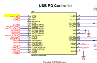
    -> Using the default configuration of the board I checked with the oscilloscope that PP_EXT_EN pin is driven high when the 20V PDO is used, so the external path is enabled in that case. 

    Yes, the 987 is capable of supplying 5A. I was able to use a 987EVM and an electronic load to negotiate a 20V contract and draw 5A. Due to some limitation of the buck converter and barrel voltage(Vout too close to Vin), the EVM does get noticeably undervolted (drops to 18V) but I do not have any issues with the device cutting out at 3-3.5A. 

    -> In your tests, which setup are you using? Two TPS65987EVM boards, one for sourcing and one for sinking?

    Thank you for your support!

  • Hi Carlos,

    I took a look over your project and did not see anything stand out.

    Can you provide a PD log during the overcurrent event. We want to see if there is a reset signal coming from the PD or if it is just shutting off.

    In your tests, which setup are you using? Two TPS65987EVM boards, one for sourcing and one for sinking?

    I tried two test setups and both were able to provide 5A to an electronic load using a TPS65987EVM as the power source. (both with VBus drooping).

    For the TPS65987EVM, I used this .pjt file:

    /cfs-file/__key/communityserver-discussions-components-files/196/TPS65987EVM_5F00_20V5A_5F00_Source.pjt

    Setup 1

    I used the TPS65987EVM as a source and have a Passmark USB-C E-load. I think this is the device we are using. (https://www.passmark.com/products/usb-power-delivery-tester/index.php) This device has software that allows me to control the load current voltage, and negotiate a PDO

    Setup 2

    I used the USB-DUO-EVM sink portion and attached a bench E-load through the PPHV and GND testpoints.

    This the .pjt file is use for the DUO EVM. It should be the same as the default project, except I increased the 20V sink PDO max current to 5A.

    /cfs-file/__key/communityserver-discussions-components-files/196/-TPS65987_5F00_DUOEVM_5F00_20V5A_5F00_Sink.pjt

    Please try these out and see if they work.

    Thanks and Regards,

    Chris

  • Hi Carlos,

    Another update: I loaded the project you shared (below) onto an EVM and can get 20V/5A sourcing with the passmark usb-c electronic load.

    TPS65987EVM 100W_test.pjt

    The only differences between our test setups appear to be the power source, the cables, and the load used.

    Thanks and Regards,

    Chris

  • Hi Chris, 

    Thank you for your update. If you can use my .pjt with no issues then the problem seems to be in the cable or the load (I think I can rule out the power source). I will try different cable and load configurations and I'll share the results. 

    Thanks,

    Carlos

  • Hi Carlos,

    If you have another 20V/5A usb-c source, it may be worth trying separate parts of the system independently as well (just the source board/just the sink board). The EVM's could have gotten damaged at some point.

    There could potentially be issues with the EVM as well. One thing I would recommend checking is the J4/J5 pin header placement and to be safe, we can also make sure our s4 switch is identical on the TPS65987EVM.

    J4: Jumper connecting SYS_PWR to PP_HV1

    J5: Jumper connecting VAR_DC to PP_HV2

    J6: No jumper

    S4: only switch 4 is on.

    Thanks and Regards,

    Chris

  • Hi Chris, 

    I have tried with your Setup 2 for the sink and I finally was able to source up to 5A. I was focusing in the source but the problem was an incorrect configuration in the sink side. Thank you very much for providing this setup project file.

    Setup 2

    I used the USB-DUO-EVM sink portion and attached a bench E-load through the PPHV and GND testpoints.

    This the .pjt file is use for the DUO EVM. It should be the same as the default project, except I increased the 20V sink PDO max current to 5A.

    /cfs-file/__key/communityserver-discussions-components-files/196/-TPS65987_5F00_DUOEVM_5F00_20V5A_5F00_Sink.pjt

    Please try these out and see if they work.

    Just for confirmation, I was using the exact EVM jumper and switch settings as you:

    There could potentially be issues with the EVM as well. One thing I would recommend checking is the J4/J5 pin header placement and to be safe, we can also make sure our s4 switch is identical on the TPS65987EVM.

    J4: Jumper connecting SYS_PWR to PP_HV1

    J5: Jumper connecting VAR_DC to PP_HV2

    J6: No jumper

    S4: only switch 4 is on.

    Thank you very much for your support!!!

    Regards, 

    Carlos

  • Hi Carlos,

    Glad you got it working!

    Closing this thread now.

    Thanks and Regards,
    Chris