This thread has been locked.

If you have a related question, please click the "Ask a related question" button in the top right corner. The newly created question will be automatically linked to this question.

BQ27220: BQ27220

Part Number: BQ27220

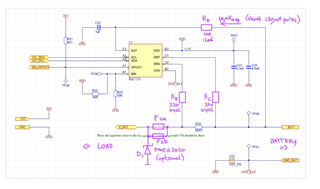
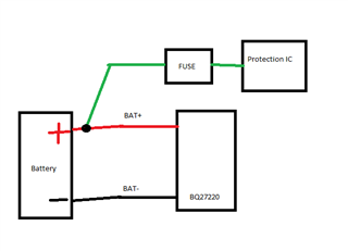
I have a question about the BQ27220 circuit design. I used the original circuit to measure the battery, but I want to add 3 resistors in the line of the BAT, SRP, and SRN, as is shown in the image you can see 3 resistors Ra, Rb, Rc (purple text) has been added in series with the chip to provide protection against SCF (Single Component Failure). I just want to know if is this allowed. no influence of the battery measurement?
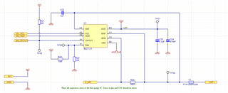
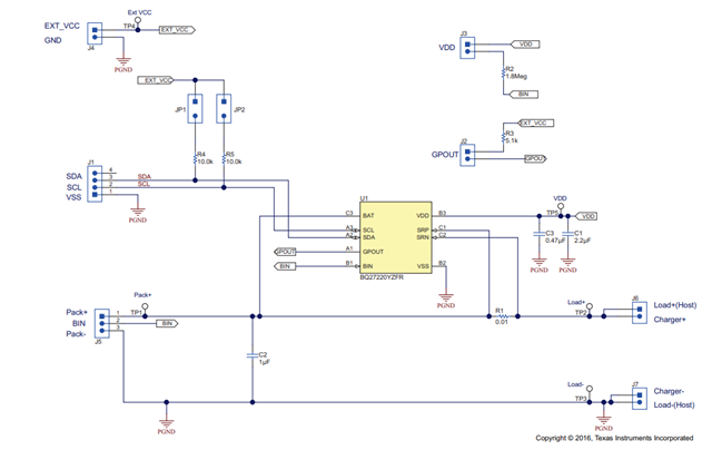
schematic:

  • Hello,

    For Ra, if a resistor is used, we typically recommend very small resistors like 5Ohms. This is because BAT pin is the battery voltage measurement input, and if a large resistor is used then voltage measurement might not be accurate for your application due to voltage dropping in the resistor (it might be ok for your application, you should test it).

    For Ra and Rb, we recommend 50 Ohms. Current protection detection may be a bit slower if 330 Ohms is used. If 330 Ohms will be used, I suggest you test it since we have not characterized it.

    Regards,
    Jose Couso 

  • Hi Jose,

    Ok, understood, thanks, but what if I place a fuse directly in front of the battery and do not use any other resistors in the lines? which approach is better and has less influence on the battery measurement? So in the following image, you can see I removed all the Resistors (Ra, Rb, Rc) and moved the Fuse (F1) to the battery side.

  • Hello Farhad,

    Adding the fuse instead of the resistors has less influence on the battery measurements. 

    Have you looked at our EVM design? You can reference here to check your schematic. I would double check the SRP and SRN connections.


    Regards,
    Jose Couso

  • Hi Jose,

    Yes, I already knew this circuit, I also have the EVM board, but if you consider the Single fault component then you need some actions to protect the circuit for safety.
    for example, if the C2 blows up and makes a short circuit, then you need protection. therefore you can have a simple PTC fuse in front of the battery or use resistors as I did in the first circuit.

  • Hello Farhad,

    I agree, I do not see any problems using a fuse. I said using a fuse has less influence on the battery measurements than using resistors.

    Regards,
    Jose Couso

  • Thanks, Jose for the answer, But I am concerned about the fuse put in front of the battery, for instance, if you draw 2A from the battery, then there is about a 120mA drop over the fuse, which I think could influence the measuring!

  • Hello Farhad,

    I understand your question and concern. 

    To prevent voltage drop on the gauge readings, normally we place the FUSE in parallel with BAT+. Please see below for more details.


    Regards,
    Jose Couso

  • Hi Jose,

    Thanks for the diagram, But this is not what I want, any way I think I could find another way to solve the problem.