This thread has been locked.

If you have a related question, please click the "Ask a related question" button in the top right corner. The newly created question will be automatically linked to this question.

Redesign of power module PCB, need to add MPPT and Li-ion battery charger

Other Parts Discussed in Thread: TPS63802, LM5146, LM5146-Q1, BQ25798, BQ25303J, BQ24650

Hello.

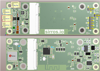
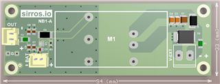
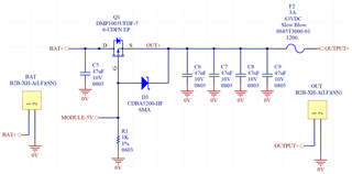
I have developed the design and layout of the PCB below, it is a power module PCB and it has 4 layers, and we have not produced prototypes of it yet. External supply is inserted at connector of right side, identified as V-EXT, the input supply voltage is from 10V to 60V, so it is compatible with 12/24/48V systems, the maximum is 60V because the breakdown(min) of the input TVS diode is 60V, it is rated for 5000W peak pulse power, but the power module identified as M1 actually can be supplied with up to 72V, so there is at least 12V off for input transients. The output of the power module M1 is 5V x 3A, and BAT connector is to connect a non rechargeable battery of LiSOCL2 type, 3.6V, 15Ah, high power type, which can supply peak currents of up to 3A. The power module M1 is isolated type (input-to-output), the manufacturer of it said to me that on it there is an internal high voltage capacitor of 1nF between pins GND and 0V. OUT is the output connector, two wires go from it to the application board that has an input power supply based on the buck-boost converter TPS63802. 
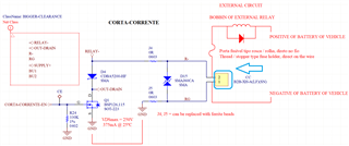
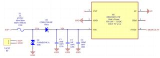


Schematic below.

We want to redesign this board and make 2 modifications:

1. Add on the output of the PCB, on the left side, a Li-ion polymer/battery (3.7V/4.2V) charger IC (circuit), in which (A) the value of the charging current can be set through the value of a resistor, (B) that operates in switching mode and not linear mode, to obtain a good efficiency, and that (C) can deliver around 1A of charging current. Please note that here the input voltage of the charger circuit is the 5V that is the output of the power module M1. QUESTION: Which ICs of TI could be used for this?

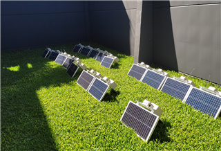
2. On the external input supply of the PCB (connector on the right side) we wanted to also be able to connect solar panels and extract the maximum energy from them. I have no experience with solar panels until now, but I know a technique to achieve this is the MPPT. From Google: "An MPPT, or maximum power point tracker is an electronic DC to DC converter that optimizes the match between the solar array (PV panels), and the battery bank or utility grid. Also, about MPPT, I have never tried to study it deeply to understand how it works. Currently our company is working with the solar panels shown in the picture below, we are working only with this single model/size, but we will start using bigger solar panels which have double the capacity of supplying energy than this one. QUESTION: Which ICs of TI could be used for this?


Any suggestions or ideas?

Thanks in advance,

Jeferson Pehls.

  • Hi. 

    I'm sorry, I have a new idea and will change the overall scheme. I will replace the power module M1 of the first picture of the previous post with a high voltage buck converter, using components and not a power module. The input supply range will keep the same, 10V to 60V, with an output of 5V x 5A, the buck IC that will be used withstands 85V for 1ms with 50% or less duty cycle.

    About the Li-ion polymer/battery charge current there will be a modification, now we need an IC/circuit nearly the same as described in the previous post, but which has a charging current capacity of 2.5A or more.

    To explain a little more, at the external supply input, we would like to be able to attach a power supply with considerably low output impedance (with high current capacity), or solar panels.

    Regards.

  • Hi Jeferson,

    Does the 5V/5A HV buck regulator need input/output isolation, or can it be non-isolated?  Saying it is a buck implies non-isolated.  A flyback could provide isolation via transformer and opto-coupler.

    Eric

  • Hi Eric.

    I know that an isolated scheme is better in terms of safety, but I believe that for this application it can be non isolated. The project is intended at first for automotive use, for use in forklifts of industries.

    Please check the pictures below observing the purple, blue and red rectangles. The second picture is the application carrier board and in it the connector of the purple rectangle is just used to connect an external button, so nothing to care about it. The connector of the red rectangle of the first picture connects to the red rectangle connector of the second picture. In the second picture the connector of the blue rectangle is to attach to an external relay, schematic on the third picture. In the second picture, the 4th connector of the bottom is just a jumper/switch to connect/disconnect the input supply to the input of TPS63802.

    Actually I don't have sure if the application requires the main power supply to be an isolated type, I wanted to work with an non isolated scheme.

    Regards.

  • The 5V/5A buck converter that I said before is non isolated.

  • Hi Jeferson,

    I think there is some delay between when you post and when I see the result.  I see the non-isolated comment now in your second posting.

    If you want a non-isolated HV buck design (85V max input) with 5V/5A output you should consider the LM5146 or LM5146-Q1 for automotive.  The LM5146 controller specifically supports up to 100V on the input and has an automotive (-Q1) option.  I used TI's Webench with your specifications to produce the following PDF report: schematic, BOM, predicted test results, etc.

    1663.WBDesign63.pdf

    If this is acceptable for the buck power supply I will forward this inquiry to the Battery Management Systems / Battery Charging Products (BMS-BCP) team for support on your other question.  Please let me know if the buck design is OK.

    Regards,

    Eric

  • Hi Eric.

    Yes, the buck design based on LM5146 is ok.

    But I have a doubt, can I directly connect the solar panel to the input of the buck converter? I was thinking that, if I connect a solar panel to the supply input, I would need to add a MPPT circuit between the supply input (connector of the right, V-EXT) and the input of the buck converter, in order to be able extract the maximum energy from the solar panel.

    Regards.

  • Hi Jeferson,

    I am in DC/DC power group so I am not familiar with MPPT, until now.  I searched previous E2E posts and saw the "MPPT" term regularly.  It seems our Battery Management group has been working with this technology.  For example, take a look at the BQ25505 home page and its supporting application notes and TIDA reference designs.

    I will forward this thread to BMS-BCP group now.  I'm sure they can give you additional recommendations.  Sorry for the mis-understanding.

    Eric

  • No problem Eric. Thank you so much.

    Regards.

  • Hi Jeferson,

    I recommend looking at BQ25798 with MPPT.

    Regards,

    Jeff

  • Hi Jeff, thanks.

    We will have 2 models of boards.

    In one of it, I'm thinking to use IC BQ25303J, in the datasheet of it is recommended to use thermistor 103AT-2 of Semitec, which has as characteristics (10K ohms 1%, B = 3435 +-1% ), would it work with one with B = 3380 +- 1%? Do I need to open a new topic for this question?

    Regards.

  • Hi Jeferson,

    If you don't use the Semitec 103AT-2, you may have to change the TS pin resistor divider values slightly using the datasheet equations on page 18.

    Regards,

    Jeff

  • Hi Jeff.

    I think that for MPPT the BQ24650 is interesting, for this project the charge controller must be a standalone type, not one controlled by a serial interface like I2C.

    I have some questions.

    (QUESTION 1) Are there other ICs from Texas Instruments that could make the same function of BQ24650, but that withstand higher input voltages? For these other possible ICs, there is no problem if they are more expensive, have more pins, etc.

    As far as I know, there are solar panels with 36, 60 and 72 cells, each cell delivering from 0.3V to 0.5V. Currently I'm considering that in our worst case we would use a solar panel with 60 cells (and with 36 cells most of times), 60 cells * 0.5V = 30V. The BQ24650 datasheet shows "Recommended Operating Conditions = 28V MAX", but shows "Absolute Maximum Ratings = 33V".  

    (QUESTION 2) So the question, would the BQ24650 be suitable for 60-cell solar panels also? Or only suitable for 36-cell solar panels?

    If I'm going to use the BQ24650, to protect its input, I'm planning to use an IC that is called "surge stopper", for example the LT4363, to limit the input voltage of the BQ24650 (any instantaneous voltage) below 31.5~32V, due the tolerance of the components. The LT4363 withstands up to 100V, so at its input I would use a TVS diode (with SMC package) in which the voltage seen on it during surges/transients probably would not reach 100V peak.

    OBS: I already found good stock for BQ24650 IC (BQ24650RVAT).

    Best Regards,

    Jeferson Pehls.

  • Hi Jeferson,

    Regarding 1, no.

    Regarding 2, above operating input voltage max of 28V, the charge stops functioning.  Above abs max of 33V, the IC could be damaged. So, the BQ24650 cannot function with with 60 series up to 0.5V panels if the 0.5V is the panel's MPP.  If the panel's VOC=0.5V, then the 80%*0.5V=0.4V which would be 24V MPP which would work.

    Regards,

    Jeff

  • Thanks Jeff.

    Today I designed a charger based on BQ25303J, I have a doubt about the datasheet, page 17 of the PDF.

    Regards.

  • Hi Jeferson,

    Correct.  That is a datasheet typo and should be RT2.

    Regards,

    Jeff