This thread has been locked.

If you have a related question, please click the "Ask a related question" button in the top right corner. The newly created question will be automatically linked to this question.

LM3492: 4 Channel LED Board with 2 LM3492 where Driver is not working

Part Number: LM3492

Hello,
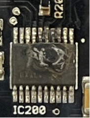
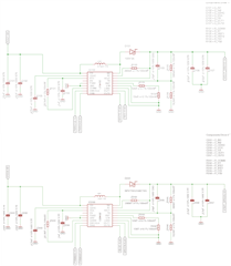
I'm working on a 4 Channel LED Board where two of the LM3492 are beeing used.
First driver is connected two the first two strings of LED and the second driver is connected
to the third and fourth sting of LED.
The board sholud be used within 24 VDC to 18 VDC and each string consits of 15 LEDs where the
string voltage is between 31,5VDC and 46.8VDC depending on the type of used LEDs in the string.
The current for the LEDs should be 50mA.

We produced several boards for testing now and we have the effect that the current is traveling
over 1A at 24VDC and at least one of the LM3492 will get very hot. But it will be different thru the
several boards, sometimes it's just one driver in some cases both of them going to be hot.
It seems that there is something wrong on the bottom line which we will not find by ourself.
Can you please double check the Scheme and give an advise?

Thanks in forward.

  • Short update.
    The Inductor L101 was changed to 180µH 0.49A, L201 was changed to 150µH 0.56A without any changes in the result.

  • hello Rene

    do you mind sharing the bom of the schematic since some values are not quite clear in the screenshot?

    let me confirm the issue you face now is that the LED current ramps to 1A rather than target 50mA? this happens to both two driver circuits in the same board? how the input and output are connected between two driver circuits? 

  • Hello Mason,

    please see the BOM here:

    C101 || GRM32EC72A106KE05L
    C102 || GRM32EC72A106KE05L
    C103 || C3216X7R2A474K160AA
    R101 || ERJPB3B5232V
    C104 || MC1210B105K101CT
    IC100 || LM3492MH/NOPB
    L101 || before 74477008 now 7447789218
    D101 || US1M-13-F
    R102 || CRCW0603280KFKEA
    R103 || ERA3VEB1202V
    R104 || MC008282
    C105 || MCA0805C100JCT
    R105 || CRCW0603383KFKEA
    R106 || CR0603-FX-1622ELF
    C106 || MC1210B225K101CT
    C107 || MC1210B225K101CT
    C201 || GRM32EC72A106KE05L
    C202 || GRM32EC72A106KE05L
    C203 || C3216X7R2A474K160AA
    R201 || ERJPB3B5232V
    C204 || MC1210B105K101CT
    IC200 || LM3492MH/NOPB
    L201 || before 74477001 now 7447789215
    D201 || US1M-13-F
    R202 || CRCW0603280KFKEA
    R203 || ERA3VEB1202V
    R204 || MC008282
    C205 || MCA0805C100JCT
    R205 || CRCW0603383KFKEA
    R206 || CR0603-FX-1622ELF
    C206 || MC1210B225K101CT
    C207 || MC1210B225K101CT

    Type of LEDs (15pcs) CLR6A-TKW

    It's not the current of the LED String its the input current of VCC which is traveling endless like a short in the circuit but there is no short inside.

    It's defenitliy comming from the LM3492. After production of the PCB I have >350kR beween VCC and ground. After powering the PCB the first time with a current limit of 1A @ 24VDC, the Drivers becoming hot imediately at a about 20 seconds, and I have 5R - 13R beween VCC and ground when i measure beween VCC and ground without powersource connected, what means something is beeing destroyed.

    There is nothing connected additionally at this time, the PIN's DIM1 and DIM2 are connected to ground by a 10kR resistor. I allready found out it's comming somewhere from the SW, RT, VOUT, FB Pins of the LM3492.
    When I let the current of VCC traveling endless both driver will explode same time.

  • hello Rene

    thanks for the information. let me review the schematic first.

  • Hello Mason,

    in the meantime I'm pretty sure I have failures in my calculation. Therefore I ask for reviewing this.

    LED String: 15 pcs. of CLR6A-TKW which have 4 LEDs per unit (RGBW) what means:

              VLED-Red-typical:    31,5V    (Ch1 on LM3492 #1 [IC100])

              VLED-White-typical:  43,5V   (Ch2 on LM3492 #1 [IC100])

              VLED-Green-typical: 45,0V   (Ch1 on LM3492 #2 [IC200])

              VLED-Blue-typical:    46,8V   (Ch2 on LM3492 #1 [IC200])

    ILED     = 50mA

    Vin        = 24VDC

    VinMIN = 18 VCD

    Viout(min) = 5Ω * ILED = 0,25V

    Due to the Design Description of the EVAL Board AN-2056 LM3492 Evaluation Board Reference Design (Rev. B) and the Data Sheet Vout Parameter
    VOut(max) should be 65V. What means:

    Vout(nom) * 2.5V / Vout(max) = VFB(nom)
                                             IC100 (White) -> 43.75V * 2,5V / 65V = VFB(nom) IC100 = 1,683V
                                             IC200 (Blue)   -> 47.05V * 2,5V / 65V = VFB(nom) IC200 = 1,81V

    By using a 16,2kΩ resistor for RFB2 as recommended I used the following to calculate RFB1

    ( VOUT(max) / 2,5V -1 ) * RFB2 = RFB1
                                              (65V / 2,5 V - 1) * 16200Ω = 405000Ω
    I used a 383kΩ first (because having on stock) now I changed to 402kΩ.

    IIN(MIN)IC100) = (VOUT(nomCH1) * ILED) / VIN -> (31,75V * 0,05A) / 24V = 0,0661A
    IIN(MIN)IC200) = (VOUT(nomCH1) * ILED) / VIN -> (43,75V * 0,05A) / 24V = 0,09434A

    IIN(max)IC100 = (VOUT(nomCH2) *2 * ILED) / VIN -> (43,75V * 2 * 0,05A) / 18V = 0,2431A
    IIN(max)IC200 = (VOUT(nomCH2) *2 * ILED) / VIN -> (47,05V * 2 * 0,05A) / 18V = 0,2614A

    For frequency I used 280kΩ for 500kHz first, now also double checked with 130kΩ for approx 1MHz.

    Therefore I have two calculations for my inductor what I have tested.

    1.
              ton(IC100) = (1 - VIN / VOUT(nomCH2 ) / fSW --> (1 - 24V / 43,75V ) / 500000Hz = 0,90µs
              ton(IC200) = (1 - VIN / VOUT(nomCH2 ) / fSW --> (1 - 24V / 45,25V ) / 500000Hz = 0,98µs

              tonMAX(IC100) = (1 - VINmin / VOUT(max ) / fSW --> (1 - 18V / 65V ) / 500000Hz = 1,45µs
              tonMAX(IC200) = (1 - VIN min/ VOUT(max ) / fSW --> (1 - 24V / 65V ) / 500000Hz = 1,45µs

              L100 = (VIN * tonIC100) / (2 * IINIC100) --> (24V * 0,9µs) / (2 * 0,661A) = 164µH --> 180µH
              L200 = (VIN * tonIC100) / (2 * IINIC200) --> (24V * 0,98µs) / (2 * 0,9434A) = 125µH --> 150µH

              ILR(L100) = ( VIN * tON(IC100)) / L100 --> (18V * 0,9µs) / 180µH = 0,14A
              ILR(L200) = ( VIN * tON(IC200)) / L200 --> (18V * 0,98µs) / 150µH = 0,17A

               IL100(PEAK) = IL100 + ILR(L100) / 2 --> 0,2431A + 0,14A / 2 = 0,32A
               IL200(PEAK) = IL200 + ILR(L200) / 2 --> 0,2614A + 0,17A / 2 = 0,32A

              L100 => 180µH | R 960mΩ | IR 0,49A | ISAT 0,5A
              L200 => 150µH | R 720mΩ | IR 0,53A | ISAT 0,56A

    2.
              ton(IC100) = (1 - VIN / VOUT(nomCH2 ) / fSW --> (1 - 24V / 43,75V ) / 1000000Hz = 0,45µs
              ton(IC200) = (1 - VIN / VOUT(nomCH2 ) / fSW --> (1 - 24V / 45,25V ) / 1000000Hz = 0,49µs

              tonMAX(IC100) = (1 - VINmin / VOUT(max ) / fSW --> (1 - 18V / 65V ) / 1000000Hz = 0,72µs
              tonMAX(IC200) = (1 - VIN min/ VOUT(max ) / fSW --> (1 - 24V / 65V ) / 1000000Hz = 0,72µs

              L100 = (VIN * tonIC100) / (2 * IINIC100) --> (24V * 0,45µs) / (2 * 0,661A) = 81,9µH --> 82µH
              L200 = (VIN * tonIC100) / (2 * IINIC200) --> (24V * 0,49µs) / (2 * 0,9434A) = 62,36
    µH --> 68µH

              ILR(L100) = ( VIN * tON(IC100)) / L100 --> (18V * 0,45µs) / 82µH = 0,16A
              ILR(L200) = ( VIN * tON(IC200)) / L200 --> (18V * 0,49µs) / 68µH = 0,19A

               IL100(PEAK) = IL100 + ILR(L100) / 2 --> 0,2431A + 0,16A / 2 = 0,32A
               IL200(PEAK) = IL200 + ILR(L200) / 2 --> 0,2614A + 0,19A / 2 = 0,36A

              L100 => 82µH | R 470mΩ | IR 0,69A | ISAT 0,78A
              L200 => 68µH | R 427mΩ | IR 0,74A | ISAT 0,84A

    I checked with those options on EVAL Board and our own PCB, but can't get it running stable, so help will be appreciated.

    Thanks in forward.

  • hello Rene

    I just noticed that the forward voltages for different LED strings are different. Since device will regulate the output voltage to a min. one that supports enough LED current. this could lead to a conflict for different forward voltage. Have you tried with two same LED strings?  

  • Hello Mason,

    No I have allways tried with the different LED Channels so this means different LED Forward voltages.

  • Does this mean it isnt't possible to have different Voltages for the LED strings on one driver?

  • hi Rene

    yes, I think so. But first of all, you may have a try to see if this is the thing.

  • Hi Mason,

    thanks for this I will double check.

    One more thing, can you give me a info about calculating VOUTMAX and VRef please.

    When I calculate VOUTMAX and try to have VRef at 1.5V it means VOUTMAX is is approx 1.66 times higher than Voutnom what means in my case it’s about 87.5V.

    Can Vout Max be higher than 65V?

  • hi Rene

    Vout cannot be higher than 65V. You can set the Vref at 1.8V to avoid over voltage when Vref is 2.5V

  • Hi Mason,

    I have now changed everything and tried to use another calculation.

    I'm using a 274kR Resistor like in the eval board for the switching frequency what should be 500kHz at 12V, as I'm using 24V I'm asuming my frequency should be 300kHz now is this correct?

    I have measured the String voltage of the worst case and I have 50V max. what makes a Voutnom of 50.25V at 50mA. Therefore I set the Vref to 1.95V to have close to 65V Vmax. For this I'm using a 402kR 0.1% resistor and a 16.2kR 0.1% resistor but my Vref seems to be at 2.2V and there is a ripple of +/- of 0.3V on it. Is this OK?

    As my switching frequency is now lower at 300kHz my L1 was changed to 330µH 0.71A IR and 1A Isat what's working pretty fine.

    After this i connected the Red sting which is a String voltage 29V on channel 1 in combination to the white stirng which is on channel 2 and has the 50V string voltage and I can not see any changes in the behaivior or the Vref voltage when driving both channels together. When using only Red the Vref is going to be 1.1V also with the 0.3V ripple on it. Is this OK as well?

    P.S. all test have been done on TI EVAL BOARD and my custom PCB with the same results.

    Thanks for the answers.

  • hi Rene

    let me confirm and then get back to you.

  • Hi Mason,

    any updates on this?

  • hello Rene

    Pls see my comments below:

    1. I'm using a 274kR Resistor like in the eval board for the switching frequency what should be 500kHz at 12V, as I'm using 24V I'm asuming my frequency should be 300kHz now is this correct?

    yes, the understanding is correct. with 24V input, frequency should be around 300kHz. 

    2. I have measured the String voltage of the worst case and I have 50V max. what makes a Voutnom of 50.25V at 50mA. Therefore I set the Vref to 1.95V to have close to 65V Vmax. For this I'm using a 402kR 0.1% resistor and a 16.2kR 0.1% resistor but my Vref seems to be at 2.2V and there is a ripple of +/- of 0.3V on it. Is this OK?

    I suppose the 2.2V is tested value, then what is the tested Vout voltage? 0.3V ripple may be coming from Vout ripple. You can add a larger output capacitor to reduce this.

    3.After this i connected the Red sting which is a String voltage 29V on channel 1 in combination to the white stirng which is on channel 2 and has the 50V string voltage and I can not see any changes in the behaivior or the Vref voltage when driving both channels together. When using only Red the Vref is going to be 1.1V also with the 0.3V ripple on it. Is this OK as well?

    Have you tried using two string white strings? when you mention no change, does it mean still not power up?

  • Hi Mason,
    My string voltage is alsmost equal now what makes the system running well on the first point of view.

    Now there is comming up another issue.
    When the PWM dimming ratio will be increased the driver shutdown immediately and will not come up anymore it seems it is defective then.

    Will a PWM ON signal shorter than 300ns destroy the LM3492?

  • Hi Rene,

    When the PWM on signal is shorter than 300ns, the internal circuit may filter the signal and treat it as low signal. In that case, the current sink will not drive any current and LED is off. When you say "the driver shutdown immediately and will not come up anymore", does the Vout still have voltage? Have you tried to reduce the PWM dimming ratio again? Or restart IC to see if it works again? Pls describe the phenomenon in more detail to help analysis.

  • Hi Yichao,
    thanks for your reply.
    My PWM frequency is 1.5kHz. When my PWM is 0 I have approx 1V on my VFB PIN. When I'm using PWM period of >=300ns my VFB will be 1.6V and 1.85V depending on which LM3492 (I have two different string voltages) I'm looking at. When I use PWM on Period smaller than 300ns I can see a increase on my VFB which will be approx 2.2V.
    When I'm playing around in the PWM ON period in the range fo 0ns - 300ns I can see a trip up (2,2V is going higher) on my VFB and my LM3492 is becoming hot again.

    After this the LM3492 is defective and will not work anymore.

  • Hi Rene,

    It seems the dynamic headroom control (DHC) is not working properly when PWM on is <300ns. DHC adjusts the VFB between 1~2.5V depends on the voltage of Iout1 pin and Iout2 pin when PWM is on in order to maximize the efficiency. When PWM is 0, current is 0, LED drop is minimal, then DHC adjust VFB to 1V. When PWM on >300ns, DHC adjusts VFB between 1~2.5V.  When PWM on <300ns, the DHC may fail to get the proper voltage of Iout1 pin and Iout2 pin during PWM on (because it's too short). Thus, VFB is wrongly adjusted to 2.2V and significantly increases the power loss of internal circuit, leading to thermal shutdown.