This thread has been locked.

If you have a related question, please click the "Ask a related question" button in the top right corner. The newly created question will be automatically linked to this question.

TPS25750: How to see the I2C register of the TPS25750 EVM live

Part Number: TPS25750
Other Parts Discussed in Thread: USB2ANY, , TIDA-050047,

Hello,

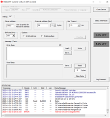
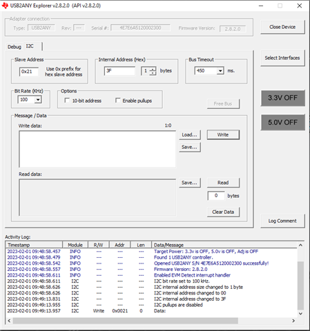
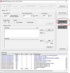
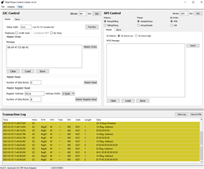
Is there a way to see the EVM register status in the Gui tool or the USB2ANY tool and if so is there a guide to do this?

I would like to see what charger type the EVM detects when connected to non PD chargers, I see the 0x3F POWER_STATUS Register,ChargerDetectStatus can report this, I would like to access this register in the EVM if possible.

Thanks a lot,

Pierre. 

  • Hi Pierre,

    Unfortunately, there is no way to read the registers using the GUI tool. This EVM also does not directly support USB2ANY, however there are a couple work arounds to do this that I can walk you through.

    1. Using USB2ANY you will need to jumper into the I2Cs lines in order to act as the master and the PD to be the slave. On the EVM R36, R37, and R41 are DNP, therefore you will either need to add a 0Ohm R or short the connection in order to access the headers to jumper into. 

    Once you have done the above step, you will then need to use jumper wires from the USB2ANY device to the EVM and use the USB2ANY to act as the master for the PD.

    Once, you have connected to the PD, you can these reference the Technical Reference Manual on specific registers.

    2. You can use a PD analyzer in order to read the negotiation between the two PD's. This might not give you the total information you are looking for but this is an option.

    Very Respectfully,

    Brandon Beader

  • Hello Brandon,

    Thanks for the prompt reply, I was thinking that TP 13 and 14 should give me acces to the slave I2C, am I correct?

    Also do you think USB to ANY explorer is the best software to reed the slave registers?

    I will try this and let you know.

    Thanks a lot,

    Pierre.

  • Hi Pierre,

    Yes, TP 13 and 14 will also work to get access to slave I2C. 

    Typically, our team uses Ardvark but USB2ANY should also be sufficient as well!

    Very Respectfully,

    Brandon Beader

  • Hello,

    I have tried to connect to the EVM using the USB to ANY tool and the USB to any explorer software.

    I conneted TP14 to J4 pin 1, TP13 to J4 pin2 and GND to J4 pin 5. TP is on the EVM and J4 is on the USB 2 ANY.

    I have set the slave address to 0x02 as I have set the ADCin to safe mode (S1/A/B/C to 0).

    I am assuming the internal address is where I should enter the register I would like to address so in this I enter the 0x29 register address for PORT_CONTROL..

    timeout is set to default and bite rate 100khz as per datasheet.

    When I do this, I do not recieve data back from pressing the read button.

    Can you help be Identify the issue?

    Thanks,

    Pierre.

  • Hi Pierre,

    I2C Slave Address is a 7-bit slave address, therefore you are writing to the incorrect slave address. 

    Decoded values to I2C address:

    Therefore, your slave I2C address should be 0x21.

    Yes, you are correct, the internal address is the register address.

    Very Respectfully,

    Brandon Beader

  • hi,

    Ah I see I did not understand the datasheet correctly.  Now the address is acknowledged, but it seems I am still missing someting because the slave is not sending data back. May be I dont understand how to input the register address, I am putting it in the internal address box, in 1 byte format. I also dont put anything in the write data box, because I want to read only the register address. I am using the register address in the technical reference manual. I am trying to read the POWER_STAUS register, so I input 0x3F in the internal address. I think I am not understanding something because this result in no data recieved:

    Thanks for your continued support.

    Kind regards,

    Pierre.

    PS I cant see in the user guide for the EVM if the slave I2C is pulled up or not, when I use a DMM on the TP13/14, the voltage is low. Is this normal?

    PPS I found that the USB to ANY isnt actualy pulling up the I2C pins as commended, when I set the PINs to GPIOs they are not going up to 3.3V but only to 0.5V, it seems there is an issue with the USB to ANY device, do you agree?

  • HI Pierre, 

    Couple items to check: 

    1. To enable pull up on the USB2ANY, you'll need to click on the 3.3V button on the right of the panel to turn it on, currently on your dashboard it's off:

    2. Make sure you're setting the correct byte size of the register (refer to the technical reference manual for exact details). Some registers are two bytes (16 bits), 1 byte (8 bits) or some other size. 

    3. How are ADCIN1 and ADCIN2 currently set up on the EVM? This would effect the slave address of the TPS25750 as Brandon mentioned. 

    4. Where are you connecting USB2ANY, is it through the Aardvark connector or the female pin headers on the underside of the EVM? 

    Thanks and Regards,
    Raymond Lin

  • Hello Raymond,

    Thanks for your advice, I have tried to enable the pull up 3.3V but SDA and SCL stay at 0V. Is there a setting to enable the slave I2C?

    Thanks,

    Pierre.

  • Hi Pierre,

    Can you check the status of the I2C pins when the USB2Any is not connected. They should have 3.3V pullups built into the EVM.

    If they are not at 3.3V, can you check the LDO3V3 pin to verify there is 3.3V there?

    Thanks and Regards,

    Chris

  • Hi Chris,

    Thanks for the sugestion. On the EVM the P3v3 is at 3.3V, the slave I2C is at 3.3V but the master I2C is at 0V. When I try to pull it up it SDA and SCl draw too much current and the lines stay at 0V. I have ordered an other EVM, the TIDA-050047 and I will try with that one.

    That issue raises a question: if i use the TPS25750 with a battery powered system. when no USB cable is not connected, the controller is unpowered and the system runs on battery power, is it possible for the I2C lines to back power the TPS25750 or is there an inbuild protection?

    Thanks a lot,

    Pierre.

  • Hi Pierre,

    Apologies for the confusion.

    After speaking with team members internally, we learned that the USB2ANY is not compatible with our device and with the TPS25750EVM. Our team does not use the USB2ANY so we were not familiar with these issues. It originally seemed like the USB2ANY supported generic I2C r/w but we could not get it to work with our EVM.

    In the past, there were attempts to use the USB2ANY with our EVM and issues were found that were related drivers and device compatibility.

    We tried using the USB2ANY with the 25750EVM on our end and reached the same point you provided screenshots of.

    As Brandon mentioned previously, our team uses the TotalPhase Aardvark to read/write I2C. The software is similar to USB2ANY, and allows you to read/write I2C to the EVM.

    You can also directly write to the I2C lines using an MCU or EC(external controller).

    Thanks and Regards,

    Chris

  • Hello Chris, 

    Thanks a lot for clarifying this, I will try to address it with an arduino and see where I cen get to. Have a nice day.

    Pierre.

  • Hi Pierre,

    Yes, apologies for the confusion.

    I would recommend referencing the TRM (specifically pg. 11) for information on how I2C read and write commands should be formatted. The format can be confusing at first.

    Unique Address -> Device Address (PD)

    Register Number -> Register in PD

    Byte Count -> # of data bytes to write/read

    Thanks and Regards,

    Chris

  • Hello,

    My TPS25750EVM failled, the I2C lines are low and pulling a lot of current. I could not find a replacement online so I have purchased the USB_PD_CHG_EVM_01. I found the user manual is a bit thin on how to program the EVM:

    the configuration file is ready to be programmed. There are a few options here to do so, the simplest is to use the Flash To Device From Current Configuration Option that connects the Tool to a connected Tiva chip on the board, for example. Another option is to export the binary using the Generate Full Flash Binary option and then using an external program, such as the Aardavark by Total Phase to program the selected configurations to the TPS25750D.

    I dont think there is a TIVA MCU on the EVM, could you explain how to use the Aardavark to program the board? including how to power the flash externaly?

    furthermore, I notice this EVM has a connector for the USB 2 Any, is this one compatible with it?

    Thanks a lot,

  • Hi Pierre,

    You are correct, there is not a TIVA on that EVM and you will have to flash device using the Ardvark flash center. For information on how to use Ardvark, I recommend going to total phase website and viewing their training on how to use their device. From the GUI you can generate your full flash image binary which you will load into EEPROM using Ardvark.

    I would recommend you do not use USB2ANY as you will have to write your own flashing scheme in order to flash binary to device.

    Very Respectfully,

    Brandon Beader