This thread has been locked.

If you have a related question, please click the "Ask a related question" button in the top right corner. The newly created question will be automatically linked to this question.

TPS61322: Loses regulation when Vin drops below 1.28v with 100mA load

Part Number: TPS61322

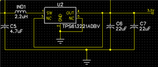
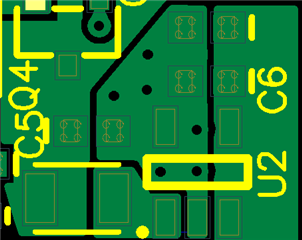
The TPS613221A (3.3v output) drops the output voltage if Vin goes below 1.28v with a constant 100mA load.  Vin 1.28v to 1.5v gives 3.3v out.  1.27v in, out=3.01v. 1.25v in, out 2.94v. 1.2v in, out 2.8v.  We tried 2 different inductors: Murata 2.2uH 80mOhm typical, 1.3A rated and Samsung 4.7uH, 130mOhm, 1.6A rated, 2.2A Isat.  With the 4.7uH, efficiency improved (lower input current), but output voltage dropped at the exact same input voltage. There's a 4.7uF cap just before the inductor and two 22uF on the output (plus the decoupling caps at several components elsewhere on the board). The PCB layout is almost identical to figure 40 in datasheet (SLVSDY5D –JANUARY 2018–REVISED FEBRUARY 2019) but without the diode and snubber (large copper connects pin 5 to GND pin 2, and large copper connects pin 3 to OUT pin 4). Note:  we added a diode and snubber, and the exact same drop occurred at the same input and output voltages.  It is a 2-layer PCB.  The bottom layer is a ground plane below this booster circuit.  Figure 3 and 4 (in the same datasheet) show the output still working even down to 0.9v input (though efficiency drops), but it does not work below 1.28v input.  Suggestions, please.


  • Hi  Jay,

    Could you tell me the input current when output voltage drop? I want to check if it is triggered current limit. Thanks.

    Regards,

    Nathan

  • Another board with 4.7uH, same capacitors. I measured Vin closer to the circuit (on C5), so the voltage when it drops is 0.1v lower than previous results with Vin measured at the power supply. Note:  the dropping output voltage caused the output current to drop (resistive load), so input current also drops.  But Vout remains BELOW expected 3.3v. 

    In figure 3, efficiency is 70% at Vin 0.9v with 100mA Iout.  Figure 4 shows Vout is 3.3v with 0.9v in and 100mA Iout.   Just using math, that is 330mW out, 471mW in (70% efficient), and therefore 524 mA in.  So it should be able to handle that input current.

    Here is how it is actually performing:

    Vin Current In (mA) Vout Current Out (mA) Power In (mW) Power Out (mW) Efficiency
    1.5 241 3.308 100.1 361.5 331.2 91.6%
    1.3 291 3.307 100.0 378.3 330.8 87.4%
    1.24 316 3.307 100.0 391.8 330.8 84.4%
    1.23 322 3.306 100.0 396.1 330.4 83.4%
    1.18 372 3.306 100.0 439.0 330.4 75.3%
    1.173 385 3.306 100.0 451.6 330.4 73.2%
    1.167 441 3.17 89.3 514.6 283.0 55.0%
    1.156 430 3.087 82.8 497.1 255.5 51.4%
    1.146 411 3.027 78.1 471.0 236.3 50.2%
    1.139 395 2.985 74.8 449.9 223.2 49.6%
    1.133 378 2.946 71.7 428.3 211.3 49.3%
    1.125 357 2.901 68.2 401.6 197.8 49.3%
  • Hi Jay,

    Thanks for providing detailed data. It seems that when Vin<1.17V, the efficiency is much lower than that in our datasheet 

    Do you have some waveforms when output voltage drop? Like Vin voltage, SW voltage, Vout voltage. Thanks.

    Regards,

    Nathan

  • Thank you for asking for a Vin waveform. Voltmeters don't tell the whole story.  We used a FET for "true shutdown" (as in Figure 36).  With Vin around 1.17v, the FET is actually turning off and on intermittently.  That, of course, brings down the output.

    When I bypass the FET, the booster works GREAT, even down to 0.838v 535mA IN, 3.30v 100mA OUT, 74% efficiency!

    I will try to find a FET with a smaller Vgs threshold.  Again, thank you.