Hello team,
I want to get feedback on the circuit I designed.
First of all, the Spec. is as follows.
1. Input voltage: 9 to 24V
2. Output voltage: 2 to 5 V
3. Output current: 200 to 700 mA
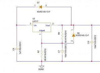
In the attached circuit
1. Input capacitor (Cin): C6 (1uF/50V/2012) Ceramic capacitor
2. Adj capacitor (CAdj): C7 (10uF/16V/2012) Ceramic capacitor
3. Output capacitor (Co): C8 (10uF/16V/2012) Ceramic capacitor
4. R8, R9 (60.4ohm/1 %/3216): Resistance will be changed according to output voltage based on 2.5V.
5. Protection Diode(D6, D7) : MURS140-13-F/ Diodes Incorporated
[Question]
1. Is the designed circuit reasonable?
2. I want to use a low-cost protection diode, do you have any parts to recommend?
3. We need to proceed with the design in a low-cost way, is there any way to lower the unit price of the parts by lowering Spec. among the above parts?
I would appreciate it if you could reply if you need any additional information.
Thanks.
Regards,
Nam