This thread has been locked.

If you have a related question, please click the "Ask a related question" button in the top right corner. The newly created question will be automatically linked to this question.

TPS26620-23EVM: supercapacitor charger design

Part Number: TPS26620-23EVM
Other Parts Discussed in Thread: TPS25947

Hi all.
I'm working with a design based in the tps26620 for a backup source with a supercapacitor.
The design was done through the design calculator tool and the schematic and the settings values are:

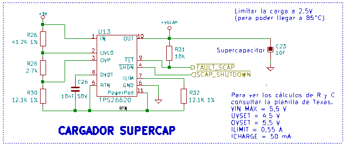
The circuit doesn't work, the efuse latches off intermediately its enabled. According to the datasheet, this behavior is due to an overload or a thermal shutdown. 
In the calculation tool I could see a possible error:

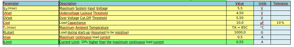
 The Cout value it is set in 10uF when its should be 10F, when I try to change the units it's not able so I try with the equivalent value (10000000). Under the original conditions, the system has no problem with power dissipation in the startup time.


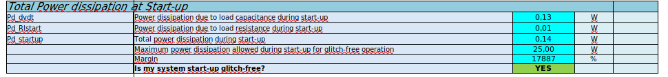
But when I change the Cout value, the system has problems with power dissipation. After some changes in the calculator I got a stable system with the following values: Cout 2000000uF and Cdvdt 100uF. (The other parameters are the same.)

When I probe the circuit with the news values, the efuse doesn't latches off, but the FLT pin in the efuse is in low state for a long time. This time (tdvdt) is too long for the efuse to get the rated voltage, but it is enough to charge the supercapacitor, then I have to turn off the efuse to prevent an overvoltage in the supercapacitor, as a consequence the efuse will never get the rated voltage and the FLT pin will always be in low state.

On the other hand, the inrush current is about 10A in the original design and about 1A in the final design.  

Then I have the following questions:

Is it correct that I changed the value of Cout from 10uF to 10000000uF (real for my design-10F supercap) in the calculator tool? or the device (tps26620) doesn't let manage a big capacitance?

With different changes in the calculator tool I could manage a maximum load capacitance of 2F (without thermal shutdown) and the maximum Cdvdt is always 100uF (for values greater than 2F), is this correct? why?

Because of the limits of current of the tps26620 (0.8A), i don't think that it's the best device for this control, is it? 

Can I improve the design with the TPS26620 to handle 10F load capacitance, or is it necessary to change the EFUSE model?

Thank you for your attention.
Best regards.

  • Hi Christian,

    I will get back within 2 days on this.

    Regards

    Kunal Goel

  • Hi Christian,

    My questions:

    1.  Can you attach design calculator here you have been working on?

    2. You want to charge supercap to 2.5V?

    3. Is there a limit on charge current?

    4. Is there a limit on cap charge time?

    Answer to your questions:

    Then I have the following questions:

    Is it correct that I changed the value of Cout from 10uF to 10000000uF (real for my design-10F supercap) in the calculator tool? or the device (tps26620) doesn't let manage a big capacitance? You can put any value in calculator. But practically charging super cap will be a problem because of thermal shutdown due to high power dissipation. We will have to keep on increasing dvdt cap to lower inrush current so that we have successful startup. But we can not keep on increasing dvdt cap because beyond a certain dvdt cap it may not have huge impact on power dissipation reduction.

    With different changes in the calculator tool I could manage a maximum load capacitance of 2F (without thermal shutdown) and the maximum Cdvdt is always 100uF (for values greater than 2F), is this correct? why?  Need to have a look at calc.

    Because of the limits of current of the tps26620 (0.8A), i don't think that it's the best device for this control, is it? Yes. There could be a better option. 

    Can I improve the design with the TPS26620 to handle 10F load capacitance, or is it necessary to change the EFUSE model. One thing you can try is keep dvdt pin open. This way device will start in current limit. You can keep current limit lowest possible. This way we can lower down inrush current without increasing dvdt cap. 

    Useful app note : www.ti.com/.../slva920

    Regards

    Kunal Goel

  • Hi Kunal.
    About your questions:
    1. Link to the design calculator.

    https://www.ti.com/lit/zip/slvc735


    2. Yes, if I guarantee 2.5V, the device could work up to 85ºC (requirement).
    3. 0.55A
    4. No, but the faster the better.
    Thanks for the application note.
    I'll try to keep the dvdt pin open and let you know how it goes.
    Thank you very much,
    Regards.

  • Hi Christian,

    Were you able to test with dvdt pin open? 

    Regards

    Kunal Goel

  • Hi Kunal.
    Yes, I was, but the results are the same as I got with the original design (Cdvdt 10nF), I mean, the efuse latches off and the supercap doesn't charge.
    On the other hand, I tested the circuit with Cdvdt = 100uF (maximum) and a supercap of 5F. In these conditions, the supercap is charged, but the FLT pin is always low (fault condition or during start-up, the same as with a 2F supercap). But I noticed this:

    The only way that I was able to change the state of FLT is when I "overcharge" the supercap to 5V (nominal voltaje for the efuse).
    Then the efuse has to reach the threshold voltaje in order for the FLT to get the low state. In my case the efuse rated voltaje is 5V and the supercap 3V, then there are some ways to solve that:  I need a circuit between the efuse and the supercap to limit the voltage in the supercap, use and efuse with 3V rated voltaje or use a supercap with 5V rated voltage.
    I'll try some of these alternatives and tell you later.
    If you think of something else, please let me know.
    Best regards.

  • Hi Christian,

    You can tie output voltage to OVLO pin through resistor divider. This way when VOUT crosses 3V eFuse will turn off and supper will not charge beyond 3V.

    Regards

    Kunal Goel

  • Hi Kunal.
    I'm sorry, I don't understand.
    What is pin OVLO? Do you mean pin OVP in the schematic?
    What would the circuit look like?
    On the other hand, in the design calculator tool, I can't put a voltage below 4.2V on pins UVLO and OVP because the minimum operating voltage for the TPS26620 is 4.2V.
    Regards.  

  • Hi Christian, 

    You will have to use another device with lower UVP. Please have a look at TPS25947 device. You will have to use a minimum VIN of 2.7V for this device.

    You can use like this:

    Regards

    Kunal Goel

  • Hi Kunal.
    Thanks for your suggestion, I'll try to probe a circuit between efuse output and supercap to manage the voltage difference while I get a new device.
    Regards.

  • Hi Christian,

    Thanks. Let me know any if new updates.

    Regards

    Kunal Goel