This thread has been locked.

If you have a related question, please click the "Ask a related question" button in the top right corner. The newly created question will be automatically linked to this question.

BQ27421-G1: incorrect readings

Part Number: BQ27421-G1
Other Parts Discussed in Thread: EV2400, BQSTUDIO, BQ24230

We are currently using the BQ27421 in our product.  The default design capacity is G1D = 3060.  We are using a 450 mAHr battery in our product.  If I read the STATE OF HEALTH, STATE OF CHARGE and REMAINING CAPACITY using the default, I get some numbers that look ok.  they are not correct due to the difference in the Design Capacity value.  If I change the Design Capacity to 450 from the default of 3060, the number look totally wrong.  For example, I see the new design capacity number, but the
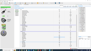
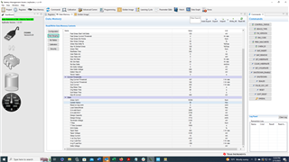
Here is the before:

Battery Voltage (mV) = 3855
Battery Current (mA) = 86
Battery Temp (C) = 22.65
State of Charge % = 42
State of Health % = 95
Design Capacity (mAH) = 3060
Remaining Capacity (mAH) = 1201
Full Charge Capacity (mAH) = 2877


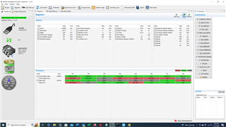
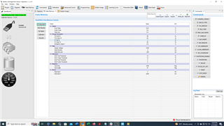
and here is the after

Battery Voltage (mV) = 3860
Battery Current (mA) = 86
Battery Temp (C) = 22.85
State of Charge % = 0
State of Health % = 95
Design Capacity (mAH) = 450
Remaining Capacity (mAH) = 0
Full Charge Capacity (mAH) = 0

Why am I getting bad readings?

  • That's because the gauge will re-calculate cell resistance (scale it up by a factor of 3060/450 = 6.8). If the current is 86, then the gauge calculates a lower open circuit voltage from the voltage and current measurement (3860mV - 86mA * cell resistance), which then leads to higher depth of discharge, which causes 0mAh remaining capacity.

    Please use the quick start guide https://www.ti.com/lit/pdf/sluuah7 to configure the gauge and make sure that there is no current flowing when you issue the SOFT_RESET command. 

  • I'm still a bit confused.  I did reference the quick start guide when I wrote the code. I think the confusion comes into play with the specific part I am using and the 'fast hibernate'.  After I setup the new parameters, I can read them back just fine.  I can even restart the code and the values remain the same.  However, as soon as I pull the charger power off (unit running on battery) it seems as though the values get reset to the original defaults.  Do I need to configure them elsewhere (NVMEM) or can I stop the device from going into fast hibernate so quickly?

  • Also, in your original response, you mention making sure there is no current flow through the device when I issue the soft reset.  A.  When am i supposed to issue that soft reset and B. I don't think it's possible to have no current flow since this is a battery operated device and the battery is always charging or discharging.

  • I was referring to the development phase for the gauge. To use this gauge with best accuracy, you must run a learning cycle using the TI tool chain (bqStudio, EV2400, gauge EVM) with your cell and let the gauge learn chemical capacity and resistance profile. With this setup, it's possible (and mandatory) to use a relaxed cell with no current when issuing the SOFT_RESET command.

    In the actual implementation, after loading the golden image (=the result from the development phase), there will always be an initial error because of the unavoidable current (like you wrote). This will then self-correct when the gauge detects a relaxed cell condition or at synchronization points (e.g. full charge).

    If you omit the learning cycle and just use the quick start guide settings in your target application (e.g. you write this with your host uC in the driver when ITPOR = 1 (and only then!!!), then the gauge will take longer to reach optimal accuracy because on top of the initial cell state error, the gauge will use an approximation of chemical capacity (it will use Design Capacity) and cell resistance (it will use a scaled version of the built in default profile) until it can learn both chemical capacity and cell resistance profile during regular use.

    About fast hibernate: This *must* be disabled as explained in the TRM. The idea is to let the gauge go into hibernate mode immediately after production before shipment so once the product is put into service, you must configure the gauge to not use fast hibernate:

  • I will order the necessary parts to do the development phase.  In our previous version of our product we used a gauge that was much easier (also much less powerful), thus some of this is new to me.  So a couple of questions: (1) how does one load a 'golden' image.  For now I will work without the golden image until I get the parts needs to get that.  As such, I'm trying to determine how to disable the fast hibernate.  You reference the TRM...not sure what that is.  Is disabling the fast Hibernate as simple as setting the parameters you show above. if so, are those done basically in the same manner as the other protected parameters (unseal, block read, checksum modify, checksum, seal?

  • The Golden Image is in FlashStream format. See https://www.ti.com/lit/an/slua801/slua801.pdf for details.

    The TRM is the Technical Reference Manual. https://www.ti.com/lit/pdf/sluuac5

    Yes, Fast Hibernate are parameters that are accessed like all other parameters. Same process.

  • OK.  If I understand this correctly, I can use these two items (already purchased) to create the golden image.  I can then take that image and using the I2C interface configure the gauge after each POR via  this connection.  I should not have to do anything else once that is done. correct?

    https://www.mouser.com/ProductDetail/Texas-Instruments/BQ27421EVM-G1A?qs=%252BrH4t%252BeVZ2MD8Re6zFk2rA%3D%3D

    https://www.mouser.com/ProductDetail/595-EV2400

    Will this also allow me (using the BQ software and eval tools above) to disable the fast hibernate etc?

  • Correct. And you can use these tools to generate a golden image that disables fast hibernate.

  • Fantastic.  the tools will arrive on Wednesday or Thursday.  I looked at what documents I can find and I'm not sure how we connect our battery and system to the EV2400.  Is it pretty obvious or is there some document available for that?  Do we just patch this box into our I2C bus on our product?

  • You can just patch the EV2400 onto the I2C SCL/SDA lines in your product. Make sure that the I2C host on your system doesn't interfere. The EV2400's I2C bus connector is marked on the EV2400 enclosure so it's really simple. You may have to remove the pull-ups on your board if the pull-ups inside the EV2400 interfere.

  • Ok Thanks again for all your help.  I'll try this as soon as the dev stuff arrives.  Is there also a place to break the connection on our battery and tie it into the module.....or do we leave it connected normally to our product?

  • The EV2400 isn't supposed to be connected to the battery, just to the communications interface (and GND). I'd leave the battery connected to your product.

  • OK.  thank you so much for all your help.  I assume we need to let the system run through some charge/discharge cycles while connected in order for the ev module to learn correct?  How many are reccomended?

  • If you want to learn a learning cycle with the gauge already installed on a PCM or PCB connected to your cell, you can use the EV2400 and bqStudio to configure the gauge and log the progress (register log and data memory auto export). As long as your system can run charge/relax/discharge/relax cycles, it's possible to perform a learning cycle.

    www.youtube.com/watch

  • I've got teh EV2400.  I've run the updated and I have the latest software installed.  When I select the gauge it gives me a warning that this device is not supported and it may corrupt the part.  Is this ok?

  • No, this is not ok. If everything is working correctly, bqStudio will auto-detect the gauge and you don't have to select anything. Please check SCL and SDA to make sure that the levels (and edges) are within spec.

  • I'm selecting the following gauge: 0421_1_09_31-bq27421G1D.bqz
    When I select it I get a message box that says "the detected device is not compatable with this application....."  However, when I go into the app everything seems to be working fine.  what voltages are the I2C pins expecting?  I have disconnected our I2C bus from the processor, but  there are other devices on the bus that are not initialized.  The other devices are running at 1.8V. 

  • also, I am able to modify the parameters and generate the golden image file.  We are using a bare metal implementation in C and do not have a file system.  Is there some sample/source code on how to program the device over I2C with the flashstream file?

  • Hello Steve,

    If bqStudio did not autodetect the device and you still proceeded to use it, then the image file may not be correct.

  • What is the actual ID that is detected? Please attach a screenshot of the dialog that pops up when you start bqStudio (where you incorrectly select the gauge).

  • Please copy this file into the config folder of bqStudio and re-try: 0421_1_09_30-bq27421G1D.bqz

  • Now when I start the studio, it opens up without me having to select a part...is that correct?

  • and is there someplace I can find the TI battery library for the flashstream

  • Yes, that's correct. What library are you looking for?

  • in the flash stream file....they show a bunch of code both .c and .h   I was hoping to find that somewhere....

    9SLUA801 – January 2017
    Submit Documentation Feedback Copyright © 2017, Texas Instruments Incorporated
    Gauge Communication
    Appendix A
    SLUA801 – January 2017
    Source Code
    A.1 gauge.c
    //Battery Gauge Library
    //V1.0
    //© 2016 Texas Instruments Inc.
    #include <string>
    #include "gauge.h"
    #define SET_CFGUPDATE 0x0013
    #define CMD_DATA_CLASS 0x3E
    #define CMD_BLOCK_DATA 0x40
    #define CMD_CHECK_SUM 0x60
    #define CMD_FLAGS 0x06
    #define CFGUPD 0x0010

  • essentially the file that will take the GMFS file (I will have to have it as a header file compiled into the program since we don't have a file system) and read it in and send all the I2C commands to the gauge

  • The code is in the SLUA801 app note. It's intended to be an example. A starting point. I compiled this several years ago for a TI ARM board to make sure it works. You can copy-paste the code from the app note into your development system or use it on a PC to write a flash-stream to C header converter.

  • Thanks.  I re-wrote my code and it seems to work ok now with regards to reading the flashstream file and setting up the battery.   Can you take a look at my setting below.  I'm still getting a bit of an odd reading.  We are using a 450 mAHr battery with a fast charger current of 87mA (.2C).  We are using the BQ24230 for our charger IC. 

  • My recommendations are to also set Design Energy accordingly.

    Quit Current must be set to rate that's higher than Taper Current (otherwise the gauge will exit charging state before it can detect a charge termination).

    Avg. I/P last run should be set to a rate close to your typical load (this is what the gauge uses to estimate capacity during discharge simulations).

    Terminate Voltage is fairly high. FCC should increase, if you set it lower (e.g. 3000mV).

  • Ok.  I'll change those settings.  Something else I can't seem to get working is the 'project' within bq.  I start a new project and get the first group of questions answered, but not sure how to advance the screen......am i missing something?  I'vet tired saving to gauge, reading from gauge, defaults etc....

  • another question.  Avg I Last Run and Avg P Last Run.  I assume this is average current and average power.  These are shown as .1Hr rate.  I assume that if our steady state current in normal operation is about 87 mA for example.....the Avg I Last Run would be 8.7 correct?

  • The idea is to save the gauge data memory contents after it was configured wither with Q&A or directly. There is no "project save" as in the traditional sense. What you enter in the configuration dialogs gets written to the gauge's data memory and this can be saved with either "Golden Image" to a FlashStream file or under "Data Memory -> Export" as a csv file.

    Avg I/P Last Run are relative to Design Capacity. If you have a 87mA average load, Avg I Last Run will be 10 * DesignCapacity[mAh] / 87mA.

  • I feel like i have everything setup correctly, but I'm still getting something that doesn't make sense.  See below.  Our charge current is 87 mA and so our taper current is 8.7 mA per the BQ24230 design.  I don't understand why when the current into the battery is at 0mA, it still only shows 84% for state of charge.  Also, sometime when I switch from charging to battery and back, the parameters on the gas gauge get reset to the defaults.  Our unit is not resetting as I watch the code and it never resets or powers down.  Any idea on either of these issues?

    Battery Information
    --------------------------------------
    Battery Voltage (mV) = 4196
    Battery Current (mA) = 14
    Battery Temp (C) = 22.45
    State of Charge % = 83
    State of Health % = 94
    Design Capacity (mAH) = 450
    Remaining Capacity (mAH) = 352
    Full Charge Capacity (mAH) = 429
    bat?
    Battery Information
    --------------------------------------
    Battery Voltage (mV) = 4196
    Battery Current (mA) = 10
    Battery Temp (C) = 22.45
    State of Charge % = 83
    State of Health % = 94
    Design Capacity (mAH) = 450
    Remaining Capacity (mAH) = 352
    Full Charge Capacity (mAH) = 429
    bat?
    Battery Information
    --------------------------------------
    Battery Voltage (mV) = 4196
    Battery Current (mA) = 9
    Battery Temp (C) = 22.45
    State of Charge % = 83
    State of Health % = 94
    Design Capacity (mAH) = 450
    Remaining Capacity (mAH) = 353
    Full Charge Capacity (mAH) = 429
    bat?
    Battery Information
    --------------------------------------
    Battery Voltage (mV) = 4191
    Battery Current (mA) = 0
    Battery Temp (C) = 22.45
    State of Charge % = 84
    State of Health % = 94
    Design Capacity (mAH) = 450
    Remaining Capacity (mAH) = 362
    Full Charge Capacity (mAH) = 432

  • You must make sure that the charge termination detection is configured correctly and that the gauge detects the full charge. Your Taper Current is 8.7mA. Your Design Capacity is 450mAh. Taper Rate should be set so that the charging current stays on for at least 80 seconds (absolute minimum requirement) after the current drops below the current for Taper Rate. TI recommends 15% higher (see https://www.ti.com/lit/ml/sluuah7b/sluuah7b.pdf), so in this case 8.7mA*1.15 = 10mA. With Design Capacity = 450mAh, Taper Rate becomes 10 * 450mAh/10mA = 450 [0.1h]. This is a very low current and I think it's better to set the Taper Rate to 400 (=11.25mA threshold).

    You also must make sure that the gauge stays in charging state, hence Quit Current must be set to a value > 400. For example 450. Otherwise the gauge will exit charging state before it can detect a full charge.

    Also, please set V at Chg Term to 4191mV so that the gauge will "know" from the start where charging actually will stop.

    About the resets: Once the gauge is configured and operating, you must not issue more than 2 standard commands per second (see https://www.ti.com/lit/ds/symlink/bq27421-g1.pdf, 8.5.4.3) because when the gauge is actively evaluating the cell's behavior, it may cause a watchdog timer reset if the host issues more than 2 standard commands per second. You can check this with WDRESET (see https://www.ti.com/lit/ug/sluuac5c/sluuac5c.pdf, 4.1.1). If WDRESET is 1, then you issued commands too fast. If WDRESET is 0 then there's an electrical problem on your circuit board that causes a reset.

  • Getting very close.  Can you help me understand how remaining capacity and full charge capacity are calculated?  Also, how does state of health get calculated?

    This is what I am reading.....

    bat?
    Battery Information
    --------------------------------------
    Battery Voltage (mV) = 4192
    Battery Current (mA) = 9
    Battery Temp (C) = 22.15
    State of Charge % = 99
    State of Health % = 80
    Design Capacity (mAH) = 450
    Remaining Capacity (mAH) = 362
    Full Charge Capacity (mAH) = 368
    bat?
    Battery Information
    --------------------------------------
    Battery Voltage (mV) = 4191
    Battery Current (mA) = 0
    Battery Temp (C) = 22.25
    State of Charge % = 99
    State of Health % = 80
    Design Capacity (mAH) = 450
    Remaining Capacity (mAH) = 362
    Full Charge Capacity (mAH) = 368

    and here are my settings:

  • RM is calculated by running a discharge simulation for a specific load and temperature from the present depth of discharge (e.g. from an OCV measurement or OCV + coulomb count) to simulated voltage dropping below terminate conditions (Terminate Voltage + Delta Voltage).

    FCC is RM + initial charge (which is (present DOD - DOD at end of charge) * Qmax).

    Additional details apply but that's the basic concept. The gauge also can smooth these values as they may jump if conditions change.

    SOH = round (100*FCC(SOH load I, 25deg.C) / Design Capacity).

    FCC for SOH is calculated with a discharge simulation from DOD at end of charge to when simulated voltage for a virtual load (SOH Load I) and room temperature (plus self-heating) drops below terminate conditions.

  • OK.  I'll digest this and see if it makes sense to me.  I must still have something not properly set.  With the setting above, I still will not go over 85% SOC.  The system was in the 8-10mA range for a pretty good amount of time and this is what I get....

    Battery Information
    --------------------------------------
    Battery Voltage (mV) = 4195
    Battery Current (mA) = 63
    Battery Temp (C) = 23.65
    State of Charge % = 83
    State of Health % = 95
    Design Capacity (mAH) = 450
    Remaining Capacity (mAH) = 360
    Full Charge Capacity (mAH) = 433
    bat?
    Battery Information
    --------------------------------------
    Battery Voltage (mV) = 4195
    Battery Current (mA) = 46
    Battery Temp (C) = 23.65
    State of Charge % = 84
    State of Health % = 95
    Design Capacity (mAH) = 450
    Remaining Capacity (mAH) = 360
    Full Charge Capacity (mAH) = 433
    bat?
    Battery Information
    --------------------------------------
    Battery Voltage (mV) = 4195
    Battery Current (mA) = 41
    Battery Temp (C) = 23.75
    State of Charge % = 84
    State of Health % = 95
    Design Capacity (mAH) = 450
    Remaining Capacity (mAH) = 361
    Full Charge Capacity (mAH) = 433
    bat?
    Battery Information
    --------------------------------------
    Battery Voltage (mV) = 4195
    Battery Current (mA) = 32
    Battery Temp (C) = 23.75
    State of Charge % = 84
    State of Health % = 95
    Design Capacity (mAH) = 450
    Remaining Capacity (mAH) = 362
    Full Charge Capacity (mAH) = 433
    bat?
    Battery Information
    --------------------------------------
    Battery Voltage (mV) = 4196
    Battery Current (mA) = 18
    Battery Temp (C) = 23.85
    State of Charge % = 85
    State of Health % = 95
    Design Capacity (mAH) = 450
    Remaining Capacity (mAH) = 364
    Full Charge Capacity (mAH) = 433
    bat?
    Battery Information
    --------------------------------------
    Battery Voltage (mV) = 4196
    Battery Current (mA) = 9
    Battery Temp (C) = 23.75
    State of Charge % = 85
    State of Health % = 95
    Design Capacity (mAH) = 450
    Remaining Capacity (mAH) = 366
    Full Charge Capacity (mAH) = 433
    bat?
    Battery Information
    --------------------------------------
    Battery Voltage (mV) = 4191
    Battery Current (mA) = 0
    Battery Temp (C) = 23.75
    State of Charge % = 85
    State of Health % = 95
    Design Capacity (mAH) = 450
    Remaining Capacity (mAH) = 366

  • Does the FC bit ever get set in your setup? If SOC stays below 100%, then the gauge does not detect a full charge. This is most often due to Quit Current causing the gauge to exit charging state before the current dropped below the current defined by the taper rate. The next most likely reason is that the current doesn't stay reliably below the current defined by the taper rate for at least 2x 40 seconds (80 seconds minimum).