This thread has been locked.

If you have a related question, please click the "Ask a related question" button in the top right corner. The newly created question will be automatically linked to this question.

LM21215A: Frequency change to 250KHz

Part Number: LM21215A
Other Parts Discussed in Thread: TPS62873-Q1

Dears:

when input=3.3V, output use DAC to do ADJ, customer found that LM21215A work frequency will change to 250KHz and output voltage ripple will up to 50mV.

we tried to remove capacitor C37 showing in schematic and work frequency will change to 500KHz which is standard frequency.

Could you pl  
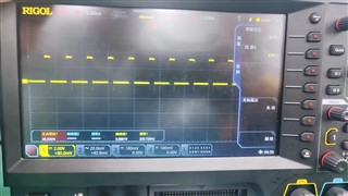
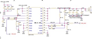
ease help check the root cause ? Thanks .

  • Hi Haiwen,

    This is a very old device.  Can you use the TPS62873-Q1 instead?  It is much smaller and provides I2C to adjust the output voltage.

    What output voltage range do you need?  Can you add Vout, SS/TRK, and the DAC voltage to the scope?  Can you send the PCB layout?

    Are there really 3 of these caps on the output? https://www.digikey.com/en/products/detail/kemet/T491C107M006AT/2336276  Are there any other caps on the output rail on other pages of the schematic?  Those are tantalum caps with almost 1 Ohm of ESR.  That is way too much ESR for a power supply--it creates a high ripple and greatly affects the control loop by adding a low frequency zero.  They could also change those caps to ceramics and see if there is an improvement.

    Thanks,

    Chris

  • Hi Chris,

    Thank you for your reply.

    What is the desired value of ESR? We have several boards. Some of them have been changed to ceramic capacitors with ESR less than 10 milliohm, which are OK. However, some of them can not work, wrong frequency, have to be changed to ESR 15 milliohm tantalum capacitor, then OK. Here is the layout, could you please help to review.

  • Hi Bin,

    Thank you for trying the lower ESR caps.  

    Ceramic caps are recommended nowadays, since they now provide very high capacitance without any inherent ESR.  A 15 mOhm tantalum is very low too and should be able to be used.  You will likely need to recalculate the compensation values, using your values of Cout and ESR.  Webench can do this for you.

    Are C28, C29, and C30 installed?  What value is used for these ceramics?  I don't see them on your schematic.  These are the input caps, which are critical to the proper operation of any power supply.

    Is there also an input filter, L32, installed?  Is this an inductor or ferrite bead?

    The layout looks maybe ok.  The input caps and output caps should be placed closer to make their loop areas smaller.

    Chris

  • Hi Chris,

    Thank you for your quick response.

    Yes, C28, C29, and C30 all installed with 47uF ceramic caps and L32 with BLM31SN500SH1. Other L,C are used as below. BTW, when the C39 was replaced by 330uF 15 milliohm tantalum capacitor, the work frequency is back to 500KHz.

    Why does the work frequency be changed to 250KHz? And any improvement suggestions?

    Thanks,

    Bin

  • Thank you for sharing Bin.  Those input caps look ok.

    Changing the output caps is changing the ripple and control loop response.  The very high ESR of the initial caps was creating the high ripple that you observed.  When using ceramic or low ESR caps, the high ripple goes away.

    The different ESR also changes the frequency response of the control loop by moving a zero.  See equation 12 in the D/S.  The zero created by the high ESR was likely making the loop bandwidth too high and this was causing large signal changes, which affected the switching frequency.

    You need to choose low ESR output caps (like you have been using most recently) and re-compensate the device by adjusting the values of R14, R15, R21, C37, C46, and C47.  Webench can help with this.

    Chris

  • Hi Chris,

    Thanks a lot.