This thread has been locked.

If you have a related question, please click the "Ask a related question" button in the top right corner. The newly created question will be automatically linked to this question.

TPS26620-23EVM: TPS26620 burnout during hotswap

Part Number: TPS26620-23EVM

Hi,


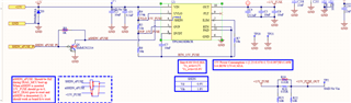
I am deisgning industrial electronics board with TPS26620 at the power supply input and hot swap does not always work. I managed to destroy two out of three identical boards. Somehow, SHDN pin gets almos short  cut with Vin pin (there is only 40Ohm between SHDN and Vin - in new, not used chip this resistance is in megaohms). SHDN pin is not used (R8 and Q1 are not populated) and line between Q1 and SHDN pin is 10mm long. Before burnout, I experienced big difference between VIN and VOUT even with no consumption at the output. I expected "smooth sailing" with TPS26620.

Best regards,

Miloš

  • eFuse gets burnout even when I change Cdvdt from 10nF to 0.68uF (there is around 1000uF of capacitance not shown on the picture connected to 15V_Fuse_OUT). I thought that too big dissipation caused by too low Cdvdt causes overheating and consequent burnout of TPS26620 - at least that suggest datasheet and spredsheet for configuring Ilim, Cdvdt, OV, UV etc

  • Hi Milos,

    Thanks for reaching out.

    I will get back before wednesday on this.

    Regards

    Kunal Goel

  • Hi Milos,

    1. You have modified EVM and testing on it or you are using your own board?

    2. At what test does device fail?

    3. Device has thermal shutdown feature to protect from FET overheating.

    4. In your case it is looking to be some pin abs max violation. 

    Regards

    Kunal Goel

  • Hi Kunal,

    1. I am testing the board which I myself designed.

    2. Device fail at normal power up i.e with normal power up of power boards which  provide 15V power supply to the board which has TPS26620 at the 15V power input.
    3. 

    4. There were one bug on the board - C7 was initialy 10nF which brings about dissipation of around 60W according to TI's spreadsheet for setting up TPS26620. I will attach spreadsheet to the post. Since I have around 1100uF on the eFuse output I placed C7=0.68uF. However, I managed to burnout one eFUSE even with C7 changed to 0.68uF.

    5. I noticed one more thing - Since capacitance at eFuse output is pretty large, it takes around 2 minutes to discharge 15V_FUSE to the level belov 0.5V. Voltage 15V (input to the eFuse) discharges much more quickly. I think and I am pretty sure that 15V_FUSE must be discharged in order eFUSE to work properly on 15V power up (input voltage to eFUSE). I added bleeder 1k resistors at 15V_FUSE to speed up capacitor disharging.

    I am still testing my device: there are 2 power boards which make 15V voltage (actually two dcdc isolated converters 24V/15V working in parallel) and 4 boards which use eFuse to connect to 15V voltage (schematic is shown above). 

    I think that somehow eFuse won't start up when output voltage is 4V or 5V and input voltage is yet to be turned on.

    TPS26624 - Design Calculator Rev1p0_BPC_SIL_PWR_15V.xlsm

  • Hi Milos,

    1. eFuse should startup fine even if there is voltage at output.

    2. Do you have some waveform showing VIN,VOUT and input current during test?

    3. Test that are you doing is very basic test for eFuse and should not cause a fail. We are somehow violating device abs max condition. 

    4. How does fail device look? Like which pins look damaged?

    5. Do you hotplug supply to eFuse or normal turn on?

    Regards

    Kunal Goel

  • 1. ok
    2. I attached the waveform - CH1-Vin, CH2-Vout, M-actually Iin measured on 1R shunt resistor placed at the Vin input.Cdvdt=0.68uF. 80mV corresponds to 80mA.
    3. I agree. I am trying to establish what causes abs max violation.
    4. SHDN pin gets almost short  cut with Vin pin (there is only 40Ohm between SHDN and Vin - in new, not used chip this resistance is in megaohms). I measured resistance with unsoldered chip.
    5. I think that it was hotplug when I burned these two boards (three chips actually - one board failed two times - 1st time with Cdvdt=10nF, 2nd time with Cdvdt=0.68uF another board only once with Cdvdt=10nF) . Since then we are trying to use hotplug as little as possible.

    I noticed that in speadsheet I sent you in previous post that algortithm suggest a lot bigger capacitance Cdvdt.
    I placed 0.1A as expected current and in that case it suggests around 5.6uF. Do you think that having 10nF and later 0.68uF for Cdvdt burned the device?

    For datasheet example (10.2.2.4.2 Case 2) 24V, 0.1A, 96R consumer, Cout=22uF  Cdvdt=10nF works perfectly,
    For my case (24V, 0.1A, 150R consumer, C=1100uF) Cdvdt must be 5.6uF. Otherwise, the chip will burnout according to spreadsheet.
    I think that here I break abs max ratings.

    Here is how my PCB looks like:

    PCB is 6L, these are top and bottom layers. Layers 2 and 4 are GND (not connected to RTN).

    This is just top layer:

    My RTN plane area is around 0.5cm2 and just on the bottom. Do you think that can be an issue?
    I mean, the current is too small to burnout the chip. When I place my finger on the chip I do not sense heating. 
    eFuse chip temperature is less than 40C, during start up or later during operation. I placed bleeder resistors at eFuse output to help output
    capacitance discharge.


    Regards,

    Miloš

  • Hi Milos,

    1. The dvdt cap will decide whether you will have successful startup or not.  Failed startup does not mean device will damage. Fail is not related to dvdt cap value.

    2. Every time you hotplug(meaning connecting an already on supply to eFuse VIN) supply to the efuse , eFuse is damaged? Can you share damaged device image?

    3. Can you try powering up by connecting some external supply to efuse VIN when supply is off. And then turn suppy on. I want to see if issue is related to supply hotplug or not.

    4. In the waveform you shared efuse did not damage , right? This waveform looks fine. Did you hotplug supply to eFuse in attached waveform?

    5. Apart from eFuse nothing else is damaging?

    6. Can you repeat hotplug test again by disconnecting load caps? Just want to see if issue is related to high output cap.

    Regards

    Kunal Goel

  • Hi Kunal,

    Yesterday I managed to burn one more chip. It might be my probing with a multimeter, but I am not sure. I might have made contact between Vin and some of the pins (UV, OV, or SHDN)...I don't know.

    1. This is reassuring, but I still do not know what the spreadsheet suggests. For example,
    for Cdvdt=10nF, chip dissipation is a few tens of W - the spreadsheet warns of changing the Cdvdt value.
    2. I didn't save the damaged chips, but all of them have bump on the plastic casing close to the GND pin.
    3.
    4.  No, eFuse worked ok.
    5. No, other components are ok 
    6. I took an empty board and started soldering component by component. First eFuse and its components with only 20nF at the output. Then I added 2x470uF and repeated tests - first turning on the laboratory power supply, then hot plug to the powered backplane. I tried hotplugging with and without big caps 20 times (or even more) and there were no failings. 
    Then I took a populated board on which I burned eFuse yesterday, soldered a new chip (with Cdvdt=1uF) and repeated tests which I performed on the board with only eFuse and surrounding elements and everything was ok. I noticed that on all burned chips pin 6 (GND) is welded to the PCB pad, so I destroyed that pad during unsoldering damaged  eFuse.
    All in all, my action was triggered when one of the boards (there are 4 boards with eFuse - 3xPCB1 and 1xPCB2) failed to start-up during normal turning on (not the hotplug). You said that Cdvdt can be the reason for that.

    I sincerely hope that all the fuss is my fault (no eFuse was burned until I started searching what was the problem) and that no eFuse shall be burned by hotplugging. However, I cannot say that I dimensioned Cdvdt properly and it may happen what you suggested in 1).
    If I have 1000uF out caps, current through eFuse of 100-200mA, what would be the range of Cdvdt capacitance which I could use?
    Best regards,
    Miloš
  • Hi Milos,

    If you are also facing failed startup issue then increasing dvdt cap will help.  As per calculator you can choose dvdt cap above 0.3uF to limit charge current below 200mA and have successful startup.

    Regards

    Kunal Goel