HI TI,
Could you help to confirm the correctness of the schematic? Thanks.
Br,
Delun
This thread has been locked.
If you have a related question, please click the "Ask a related question" button in the top right corner. The newly created question will be automatically linked to this question.
HI TI,
Could you help to confirm the correctness of the schematic? Thanks.
Br,
Delun
Hi Delun
The schematic looks good, no problem, if change the 0.22uH inductor to 0.47~0.68uH, the ripple performance will better.
xueliang
Hi Xueliang,
Got it. Thanks a lot.
I will change the inductor to 0.47uH.
BR,
Delun
Hi Kao
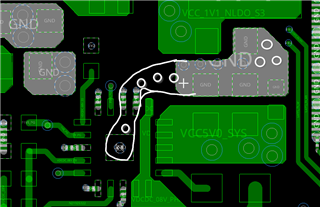
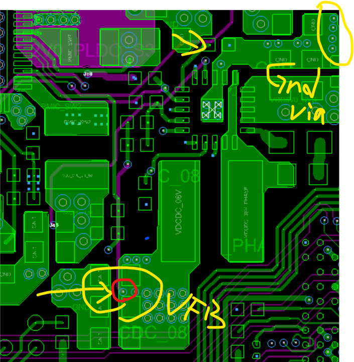
1. recommend to expand the input GND copper and add more via to cover ~10A current.

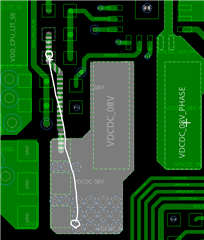
2. recommend to connect FB trace close to the far-end caps in inner layer to avoid noise interference and reduce the I*R drop of trace line.

Others looks ok!
xueliang
HI Xueliang
Thank you for your reply, I have completed the modify, please confirm whether this is correct. thanks.

BR, Delun