Because of the Thanksgiving holiday in the U.S., TI E2E™ design support forum responses may be delayed from November 25 through December 2. Thank you for your patience.

This thread has been locked.

If you have a related question, please click the "Ask a related question" button in the top right corner. The newly created question will be automatically linked to this question.

UCC21736-Q1: Unknown circuit node error in LTspice

Part Number: UCC21736-Q1

Dear Team,

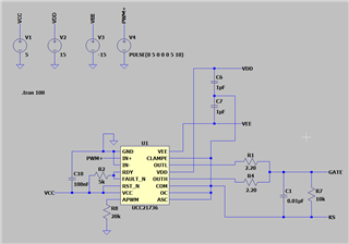
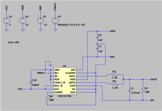
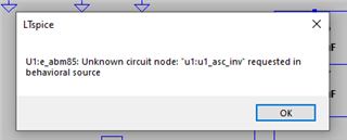
I've tried to simulate the circuit in LTspice using UCC21736-Q1 unencrypted spice model. But I'm getting the following error (U1:e_abm85: Unknown circuit node: "u1:u1_asc_inv" requested in behavioral source)

I've no idea whether the error popped up is because of the schematic or due to pspice model. Can you please help me to figure out this error!
    

Best regards,

Varun B

  • Hi Varun,

    Thanks for your interest with UCC21736 device,

    I realized that the Tx and Rx gnds are not separated. Can you please plan GND1 on the tx side separate from COM and connect the Tx side and Rx side connections approrpirately. APWM pin is connected to COM.

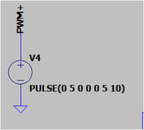
    For the PWM supply, what are the list of levels (is the list value planned as sweeping voltage)? 

    FLT , RDY are open drain and should be pulled up to VCC with 5K resistor - not connected to GND.

    Please try these changes and let us know if it helps.

    Thanks

    Sasi

  • Hi Sasi,

    Thanks for the info.

    • I've connected FLT and RDY pins to VCC with 5K resistor. The same error pops up with the folowing changes.
    • For the PWM it is planned for a 2-level 3-Phase SiC inverter.

    I didn't get you with Tx and Rx side ground connection. Can you explain it once again.

    I'm unable to share the file here but I hope the screenshots helps you.

    Best regards,

    Varun B

  • Hi Varun,

    In case of the PWM supply,  the values listed here represent what? just curious. 

    In your simulation schematics, you have tied up both COM and GND1 to be the same reference. I was recommending to separate the Tx and Rx ground. 

    Also I realized that you have short CLMPE to COM, it should not be short to COM. But connected to VEE through CAP or left open. Can you please try that?

    Let me know if it helps. Without the actual files, its tough to understand what causes this issue.

    Thanks

    Sasi