This thread has been locked.

If you have a related question, please click the "Ask a related question" button in the top right corner. The newly created question will be automatically linked to this question.

0-20V PHASE CUT OUTPUT for SOLENOID VALVE control by a 0-10V DC input signal coming from PLC

Hello.

On a 24V AC facility 

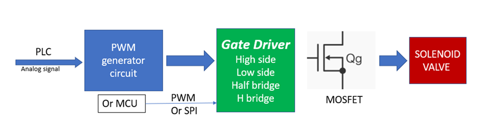
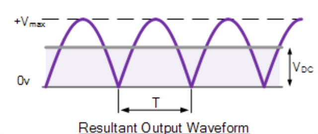
I am asking some expert if there is already available a TI driver for outputting a 0-20V PHASE CUT signal (max 120W) for controlling some old solenoid valves (24V -120W) rather than the standard analog method I have understood so far: and can be summarized in 4 stages:

  1. The 0-10V DC input signal coming from a PLC is fed into an amplifier (Op-Amp) which increases the voltage level to 0-20V.
  2. The output from the amplifier is then passed through a phase cut controller, which is used to generate a phase cut signal that is proportional to the input voltage.
  3. The phase cut signal is fed into a power stage that drives the solenoid valve.
  4. The solenoid valve controls the flow of fluid

I have searched so far in TI IC archive but not found some useful IC that can control the power stage drive that is commonly made via a Hexfet power mosfet driven by a voltage comparator.

Any help also some hints what to look up in TINA TI apart from phase margin of the OPAMP since I want to design it from scratch and avoid traps for young players would be very useful.

Thank You

  • Hello!

    Thank you for reaching out to us. I will check with an expert and get back to you on the status latest end of this week. 

    Regards,
    Martin Staebler

  • Hi Stefano,

    good day, I will follow up this question: 

    At first there is an important application note about solenoid: Link. It introduced TI solutions and solenoid application.

    I redraw the block diagram:

    PWM generate circuit: Please refer to TI design: Link, there is also a TINA simulation.

    Better is use MCU to generate PWM or even control driver with SPI (e.g. DRV8714)

    Gate driver:  

    As application mentioned, there are many options to use: high/low side, half/H bridge.

    DRV series device is TI integrated solution, you can search it in this page: Link

    You can also use a single low side gate driver,  research device : Link

    DRV Device has better integration, protection, flexible work mode.

    DRV driver proposal:

    Low/High side: DRV8714; DRV8343

    Half bridge driver: DRV8714; DRV8343

    H bridge (with MOSFET): DRV8243; DRV814x; DRV887x

    H bridge driver usually also support to config as two independent half bridge.

    Hope it's helpful for you.

    Any question pls let me know

    Thanks 

    Eason

  • Thank You Eason. I really appreciate it. I have already looked through the links but the main request from our client is to use a PHASE-CUT 0-20V method rather than PWM. Can You give me support for this method a suggest some IC's?

    Best regards and thank you so much.

  • Hi Stefano,

    Thanks for your feedback. Actually I'm also not familiar with phase cut circuit design, hope I can learn from you. 

    At first I want to know why customer prefer to use phase cut circuit, not the PWM? 

    I think the the presence of bus capacitance is critical: 

    if the output voltage after Full Wave Rectifier Circuit(below)  without bus cap, it's a AC voltage, in this situation, we should use phase cut circuit to control MOSFET.

    With a bus cap, this output will become to a DC voltage, I think we should use PWM. Is this understanding right? 

    Base on this understanding, I will suggest your customer add a 270uF(63V) bus cap to get a DC bus voltage and use PWM solution. 

    Phase cut IC Solution: 

    I don't found those IC in TI(maybe it exist).  But if there is a device you know, you can input the part number in Crosse reference tool, then you can find out the same function TI device and related technical paper in device page. 

    Thanks

    Eason