This thread has been locked.

If you have a related question, please click the "Ask a related question" button in the top right corner. The newly created question will be automatically linked to this question.

LM5116: Power Supply Stability

Part Number: LM5116
Other Parts Discussed in Thread: TPS548B27

It appears that our TI power supplies appear to be unstable. When I run the TI Webench, it complains about the low divider resistance in the feedback path, but the data sheet recommends starting with 1mA of current through R1. This yields a low resistance of 1.21 kΩ. It seems to accept the changes once I have updated both R1 & R2 to their 1.40K and 2.45K values.

According to TI Webench, the following circuit should achieve:

  • Phase Margin = 59.81°
  • Crossover Frequency = 49.66 kHz
  • Gain Margin = -13.97 dB
  • Switching Frequency = 403.13 kHz

2061.WBDesign13.pdf

From the data sheet, it states that the compensation network should be selected at least an order of magnitude less than the target crossover frequency. In this case, we would want the compensation network to yield a desired compensation network zero of 4.966 kHz. Currently the zero is at 6.412 kHz.

But from my measurements with a Network Analyzer, this is what I see:

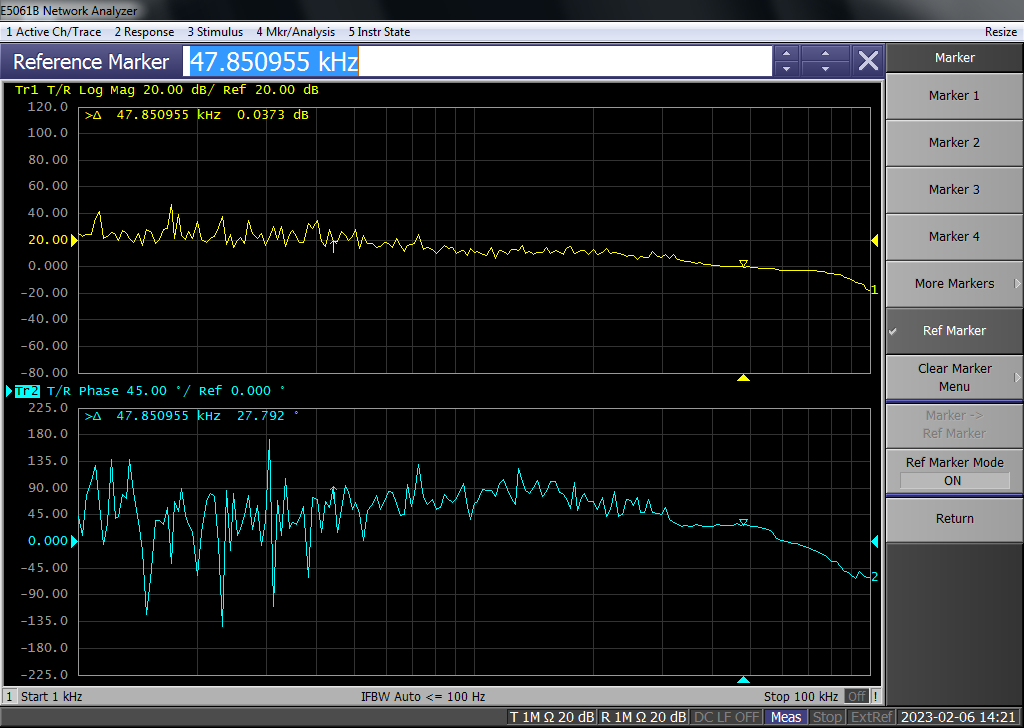
This reports the following:

  • Phase Margin = 27.792.81°
  • Crossover Frequency = 47.850955 kHz

What is wrong with the circuit above that is causing such results?

Regards,

Jeff K

  • Hello Jeff

    Please try these items

    • Increase the perturbation amplitude. Please monitor the amount of perturbation at the FB pin using an oscilloscope. 
    • Reduce band width of your network analyzer 
    • Use 'average' function in your network analyzer
    • Connect probe ground leads to the same point. For example, output capacitor ground. 
    • Twist the output wires of the isolation transformer. 

    -Eric Lee

  • The problem was a mismatch between the compensation network and the feedback resistors. The original Webench recommended 18.7K and 10.9K resistors with the current compensation network but the previous EE replaced these feedback resistors with 2.4K and 1.4K without change the compensation network.

    I found that I can either update the compensation network (auto-compensation function) or return to the original feedback resistors. Is there a recommendation as to the which is better?

  • Hello Jeff

    Good to hear you resolved the issue. Low FB resistor values are preferred if VOUT accuracy is important or the system is noisy. High FB resistor values are preferred if the efficiency at no load condition is important. 

    - Eric Lee

  • Thank you for your quick reply.

    I have two LM5116 designs that are unstable:

    1. 14-50Vin, 3.3V@6A: 
      1. I can use 18.7K/10.9K or 33K/19.1K with current compensation network (22pF || 36.5K & 680pF).
      2. I can use current divider 2.4K/1.4K with new compensation network (10pF || 5.9K & 1800pF).
    2. 14-50Vin, 5V@8A:
      1. I can use 32.4K/10.4K or 39K/19.1K with current compensation network (22pF || 52.3K & 680pF).
      2. I can use current divider 3.74K/1.2K with new compensation network (10pF || 9.09K & 1200pF).

    The third LM5116 design is:

    1. 14.5-50Vin, 12V@8A:
      1. It uses 86.6K/9.76K with current compensation network (6.8pF || 130K & 270pF).
      2. This one appears to be stable.

    I have another 1.03V power supply using TPS548B27 that is unstable also. I have already opened another TI ticket on it.

    Webench doesn't provide bode plot or phase margin information on the TPS548B27 device. It does support a load transient simulation, and this is what I get:

    Any clues as to how to compensate the TPS548B27 for load transients?  When I measure its phase margin I get:

    Crossover frequency = 36.55313 kHz and Phase margin = 34.133 degrees.

  • Hello Jeff

    I am sorry. I am not in charge of TPS548B27. You have to open new thread.

    Please try actual resistor load not CR mode electrical load with short cables on both input and output side if any chance. 

    - Eric Lee