This thread has been locked.

If you have a related question, please click the "Ask a related question" button in the top right corner. The newly created question will be automatically linked to this question.

MC34063A: MC34063 input output short issue

Part Number: MC34063A

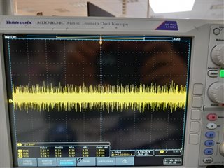
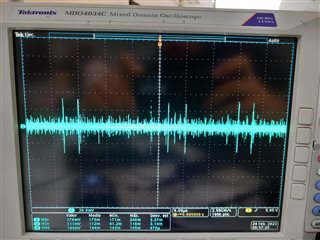
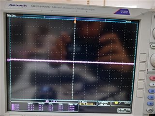
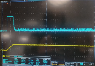
We have a problem in which MC34063 pin2 is showing short with pin1. We are using it to convert 24V DC to 5V DC. When we increase the load to 100mA with ambient temperature 25ºC the MC34063 is broken.

The aim of the circuit is to have
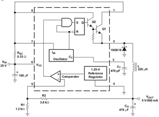
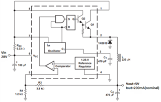
-Vin nominal 28V

- Vout 5V

- Iout maximum 300mA

-Tamb max 80ºC

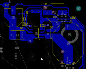
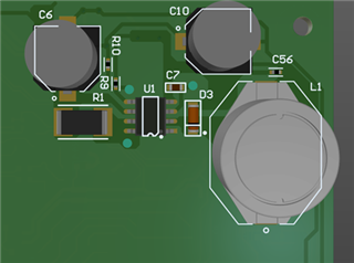
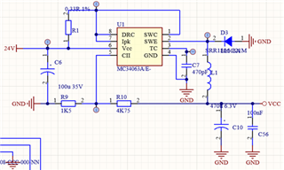
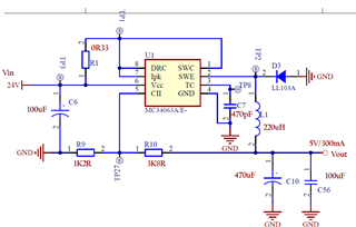
The circuit is the next one:

Could you help us please?

  • Hi Eider,

    Thank you for using E2E forums, your schematic looks or seems to be fine and the short of pin 1 and 2 means the internal BJT is breaking. Could you maybe send some waveforms and layout ? This could be a layout issue. Please send me pictures of the layout in pdf format and also if possible the waveforms of Vin, Vout, IL and current flowing from R1.

    Thank you 

    BR,

    Haroon

  • Hi Haroon,

    Vout:

                  -MAX: 5.24V

                  -MIN: 5.21V

                  -RMS: 5.21V

    Vin:

                  -MAX: 31.2V

                  -MIN: 31V

                  -RMS: 31.1V


    I-R1:

                  -MAX: 17mA

                  -MIN: 11.1mA

                  -RMS: 14.1mA

  • Hello Eider,

    The parameters of the components in figure 11 in the datasheet are calculated for VI`=24V, IOUT=500nA.
    It appears that you have simply copied that.
    For your requirements you will need to re-calculate all the components as described in the datasheet: 9.2.3.2 Detailed Design Procedure.
    I am pretty certain that the value of the sense resistor will need to be changed accordingly.

    Best regards,
    Harry

  • Hello Harry,

    Thank you for your reply.

    The data sheets says 25V 500mA. Yes, you are right, we have copied the 0.33Ohm value.

    We have 3 x 470uF capacitors in our circuit.

    The maximum nominal current is 50mA.

    We have seen the 500mA initial peak.

    We have reduced it to 50mA by placing two 100Ohm resistors before Vin.

    But it seems that, as you are indicating, we could limit that current with the Rsc resistor.

    Which will be the correct value?

  • Hello Eider,

    Thanks for sending the additional information.
    Like Harry mentioned, there is a section in the MC3x063A datasheet for calculating the Rsc resistor.

    For a max output current of 500mA, the according Rsc resistor would be 0.5 Ohms.

    However, I am still not sure why the internal BJT got damaged in the first place, as it should be able to withstand an output current of 500mA, too.
    Do you know if the input voltage went above 40V at any point of time during testing?

    Best regards,
    Niklas

  • Hi Niklas

    Thank you for the reply!

    We are sure that the input voltage didn't go above 31V

  • Thanks for the quick reply.

    Then this should not be an overvoltage issue.
    I would recommend to run tests with a larger sense resistor like calculated above and check if the issue still occurs.

    Were you able to re-create this short event behavior with several devices, or is there just one damaged IC?

    Best regards,
    Niklas

  • Hi Niklas,

    The issue doesn't occur with the adapted design. But we are able to reproduce the issue at any time with the first design.

    We will like to understand what is happening.

    Layout

    Schematic:

    When the Iout is above 200mA the short circuit issue appears.


  • Thank you for the update and the layout overview.

    I am glad to hear that the design modification fixed the issue.

    I will take another into the design and the device itself to find the initial source of the error.
    Please give me time until the beginning of next week to give you a detailed reply.

    Best regards,
    Niklas

  • Hi Eider,

    I took another look into your design and the datasheet.
    I still cannot give an absolute reason why the device broke with a smaller sense resistor.

    It might be related to the other components within the schematic.
    E.g. if a smaller sense resistor allows higher inrush currents, the inductor also need to be able to handle stronger currents. If the inductor ratings are only calculated for a max load of 200mA, the part can fall into saturation which leads to even stronger currents destroying the internal switch.

    Best regards,
    Niklas

  • Hi Eider,

    As there were no further comments, I will close this thread for now.
    If you have additional questions, please reply below to re-open the thread.

    Otherwise, feel free to click on the resolved button.

    Thank you and best regards,
    Niklas