This thread has been locked.

If you have a related question, please click the "Ask a related question" button in the top right corner. The newly created question will be automatically linked to this question.

LM74910-Q1: How to enable sleep mode?

Part Number: LM74910-Q1
Other Parts Discussed in Thread: LM74900-Q1

Hi Expert

Customer use cause as below:

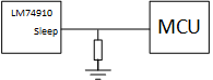
The MCU power form LM74910 output and the sleep pin default tie to GND.

when LM74910 power, EN rise slowly and sleep pin still low. when LM74910 have output and make MCU power on, the sleep pie will be pulled high.

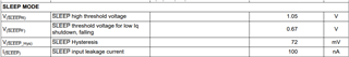
we know when EN is high and sleep is low at the same time, 74910 will move to sleep mode but base on above process, when LM74910 power on, EN will to high but sleep pin still low. Is it make device move on sleep mode?

in addition: we want to know when we want to triggers sleep mode whether is pull low sleep pin? if device doesn't build stable output(e.g. first power), sleep mode whether is be blanking?

Question 2:


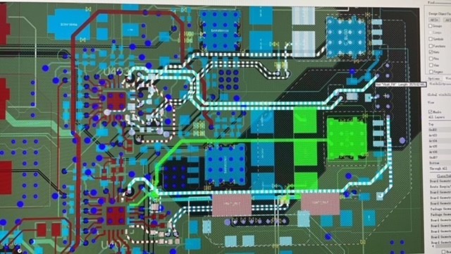
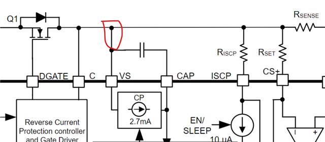
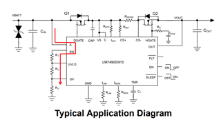
the green wire from source of Mos to CAP. Is there have any risk in too long wire?

  • Hi Meng Liu,

    Let me get back to you with a response by early next week. 

  • Hi Meng Liu,

    1. It is not recommended to startup into SLEEP mode. In sleep mode, there will be no inrush current control. While starting up into capacitive load the amount of current flow from IN to OUT will be very high if there is no  inrush current control. This can cause shut down of LM74910-Q1 due to over current in SLEEP mode and thermal shutdown. 

    Pulling SLEEP/ pin low enables SLEEP mode.

    2. VS pin requires a local decoupling capacitor of at least 0.1uF as VS pin provides power supply to all the internal circuits of the IC.

    The connects of A and C from the Mosfet Source and Drain need to be short. To ensure this the Mosfet has to be placed close to the IC. Longer connections between A and C lines can be susceptible to noise coupling and cause false reverse current turn OFF of DGATE. 


  • Hi Praveen

    thanks for your explain and it very clearly.

    I have one more question:

    customer want to choose the 100K for pull down resister. 100K*100nA=10mV<< 0.67V Is this value risky?

    Also: Do we have the maximum value of total system quiescent current?


  • Hi Meng Liu,

    Please clarify which pull down resistor you are referring to ?

    The maximum quiescent current value will be updated in the datasheet once the device is released to market. Right now this device is only in preview phase hence we do not have the entire data right now. 

  • Hi Praveen

    Customer use case as below:

    They want to choose the 100K for pull down resister. Is this value risky?

  • Hi Meng Liu,

    It depends on the MCU GPIO pin pull up and pull down strength. For LM74900-Q1, what matters is only the voltage seen on the SLEEP pin. 

    As long as the voltage on the SLEEP pin is driven <V(SLEEPF)  the device enters SLEEP mode and when the voltage on SLEEP pin is driven >V(SLEEPR) it comes out of SLEEP mode.

    The SLEEP pin draws only 100nA of current from the MCU. So, the MCu must be capable to drive current > 100nA + current drawn by the 100kohms. 

  • Hi Praveen

    I have one more question.

    How to understand total system quiescent current?

    In my understood that is include charge pump current and internal compotator and logic current like gate regulation sink current(12.3uA) and charge pump regulation sink current(15uA). System total current=external Mos's current + 630uA. 

    I also want to know, how to get this parameters value and how to get the maximum value? 

  • Hi Meng Liu,

    The  I(Q)= total System Quiescent current is the current drawn by the IC and coming out of the IC GND pin. So, this current includes current drawn by all the pins of the IC. 

    Please note that there will be one more current component which is the current flowing through the UVLO and OV resistor ladder. 

    So, the total current drawn from the input power supply would be = I(Q) + Load current flowing through the FET + current flowing through the resistor ladder

  • Hi Praveen

    Understood, thank you very much.