This thread has been locked.

If you have a related question, please click the "Ask a related question" button in the top right corner. The newly created question will be automatically linked to this question.

GPCRB: Finished Process - Negative room temperature resistance error - Negative Ra error

Part Number: GPCRB
Other Parts Discussed in Thread: GPCRA0, BQ34Z100-G1, , BQSTUDIO

Context:

  • Successfully finished the GPCRA0 process and the bq34z100-G1 is working great
  • I know for certain that the CHEMID is correct because a new one was generated by TI specifically for these cells mid 2022
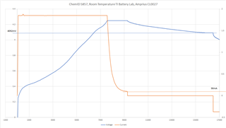
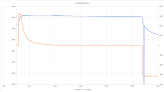
  • These are interesting cells where they need 30psi of compression on them at all times in order to perform to the manufacturer's specifications. It was out of the scope to have TI do this for me during the characterization process at the cell level. The pack currently has a type of banding around it in order to achieve this. I understand that the cells will probably behave a little different than the original CHEMID now but it's the best we can do and IT is tracking very nicely after finishing GPCRA0.
  • C/2 discharge currents for both GPCRA0 and GPCRB
  • GPCRB errors:
    • Error: negative room temperature resistance observed R=-0.00992356722138726 usually caused by wrong chem ID selection
    • Error: negative Ra R=-17.81 check data and ID selection

Thoughs/Questions:

  • I'm not surprised it didn't go perfectly with the addition of the banding;
  • What I'm really interested in is whether or not I can salvage anything from the GPCRB process; 
  • Can I still use the generated chemdat file or should I stay away from it?
  • Can the negative RA just be fudged to something reasonable or will we have convergence issues with IT if I do that?
  • Are the T Time Constant and T Rise values worth updating from GPCRB even if I don't use the generated chemdat file?
  • Which Ra grid point is negative?

    The thermal model values are still useful (assuming GPCRb data collection was done correctly. One typical mistake is to have the fan of a thermal chamber blast cold air onto the cell, which will force the cell to a specific temperature, thus rendering the thermal model values useless. This should ideally be done with the cell installed in the final product enclose in an environment with cold ambient temperature so that the data shows how the heat generated by the discharge dissipates into the environment).

  • It was the RA0 grid point. Again not overly surprising with the compression. Even GPCRA0 complained to me with "Warning: Voltage under load 4136 mV is higher than OCV 4092mV. Please check correctness of your chem ID." but the gauging was still acceptable.

    I was careful not to make that mistake of exposing the pack directly to the thermal chamber moving air. The temp sensor is embedded at the center of a 6S pack and I put an enclosure around it to emulate the final design.

    I'm glad to know that I can still use the T Time Constant and T Rise values. They do operate independent of the new chemdat file right?

    What do you think of using a modified Ra table and the GPCRB chemdat file? Is it worth doing or should I just work with the GPCRA0 parameters?

  • The chemdat file doesn't include the thermal values, just the ChemID. The thermal values are part of the gg file that GPCRb returns.

    That the loaded voltage is so much higher than OCV for grid point 0 is concerning because it indicates that you use a ChemID that doesn't cover the charging voltage that you use. Is this a 4100mV ChemID? If so, you can't use this ChemID for cells that are charged to a higher voltage because the gauge can't resolve DOD for a full charge.

  • Understood for the thermal values. Thanks.

    It is a 4250mV chemistry (5857). I also confirmed it in the description in bqstudio as well.

    Does the chemdat file indicate that it was only characterized to a max charge voltage of 4100mV?

  • ChemID 5857 was done with a max. charging voltage of 4106mV (I just checked the actual OCV tables). Did you have TI create this for you or was this one that you found in the list? If it's the former, then TI characterized it by mistake for 4100mV. If it's the latter, then this may have been done on purpose.

  • TI did create this one for me. That's very unfortunate. We had the manufacturer send their cells to Dallas and I waited for the line item to show up on the list in the chemistry database.

    What are our options for remediating this? Could we extrapolate the data to some degree in the chemistry file just to complete the OCV table?

    I am shipping out units to a customer this week so I was hoping to have all of this ironed out soon.

  • Let me check with our battery lab. It's closed today because of President's Day so I won't have the answer today. It may just be a data processing error. I hope that we have characterized the cell for 4250mV charging voltage.

  • Thank you for looking into this. I look forward to hearing what you find out.

  • What was your charging setup (voltage and taper current) for the data that you submitted to GPCRb?

  • 25.5V (6S) voltage limit, 3.125A current limit, wait for <100mA for 80sec for VCT bit to assert then cut charge and wait for OCVTAKEN

  • The 3.125A is the charging current, correct? What it the current when charging stops (taper current)? I verified the data from the battery lab. We did charge it to 4250mV CV with a 900mA taper current. The cells then relax to an OCV of 4106mV, which is fairly low. So I was wondering how you charge the cells.

    Would it be ok, if you attach the zip file that you uploaded to GPCRb?

  • Glad to know they did 4250mV. I do a 100mA taper for this specific pack. The customer is interested in maximizing UAV flight time so we go a lot longer on charging to get as high energy density as possible.

    Yeah I can attach the zip file.5127.GPCRB.zip

  • TI actually charged to a taper current of 90mA (not 900mA). So while this is good as it's close to your setup, the cell behaves differently.

    TI battery lab:

    Note how cell voltage settles at 4092mV.

    This is different from your roomtemp.csv file:

    Here it settles at 4215mV. Note that it started out at 4068mV. Then you charge 250mAh, which results in 4215mV relaxed OCV. Total discharge capacity for your log file is 7400mAh, which indicates that your are using them in a 6s2p configuration. Is this correct?

    If it's a 6s2p configuration, then 250/2 mAh = 125mAh of charge results in a significant change in OCV (4068mV to 4215mV). 125mAh is 3% of Qmax (100 * 125mAh/4008mAh) so it looks like these cells have a really steep OCV curve at low DOD and our characterization doesn't cover quite the max. OCV that you reach by charging to an effective 90/2mA = 45mA taper current.

    --> This looks negligible. Also, for better accuracy, GPCRb requires a complete charge, not just a 3% charge like in your example. If you re-submit this with room temperature log data starting with a fully discharged cell and a charging phase to full with an 180mA taper current (if you use a 6s2p pack), then I anticipate that the tool will not throw an error. Also make sure that the discharge log doesn't have a spurious measurement of 0V (like in your existing roomtemp.csv file).

  • You are correct on the 6s2p configuration. I apologize for missing that detail.

    Thank you for the guidance on starting from fully discharged on the GPCRB and for the proper taper current. 

    Good catch on the spurious 0V. I didn't think to check the log for errors before submitting.

    In the interest of time, I'd like to clarify, I likely only need to run the roomtemp test again with the new taper current and not the lowtemp test in order to clear the errors?

    Also, since this may be negligible, could I just use the GPCRB chemdat file I currently have and just modify the RA0 gridpoint or is that a bad idea?

  • I can't say if the GPCRb chemdat file is good. GPCRb usually refuses to produce a chemdat file if something is wrong so I'm surprised it even calculated a chemdat file. The chemdat file has adjustment tables for cell resistance as a function of DOD. I would think that the entry for grid point 0 is probably incorrect so there may be issues at temperatures other than 25deg.C, e.g. for the 100% SOC reference DOD (DOD at EOC).

    GPCRb isn't necessary for a custom ChemID anyways because chances are that the temperature adjustment tables that TI generated with the data from the battery lab are of higher quality than what GPCRb calculates, especially if the source data is compromised (or has data for DOD < 0.0 for this ChemID like in this case where from a ChemID point of view, the 2p 80mA taper current overcharges this cell).

    I recommend just using the original ChemID, divide all default Ra values by 2 (because of the 2p configuration), set Qmax to 4008mAh (=which is what our battery lab measured) and set temp a/k to the values from the gg file that was returned by GPCRb (this is unrelated to the R grid point and DOD problems).

  • And yes, if you want to resubmit for GPCRb, just create a new room temperature file, starting with a discharged and fully relaxed battery and set a taper current of 90mA per cell (=180mA for the battery pack).

  • Out of curiosity I did the roomtemp run again today with the new taper current and still got the same errors to a slightly lesser degree. Not too concerned about it. I am sure if I tried a few more times with higher taper currents I would eventually get it to show no errors.

    I'd say this is resolved. Your guidance and insight has helped me to better understand the whole process and gain confidence in the current settings I have. Your explanation on what GPCRb actually accomplishes resolves the need to perform it since the TI characterization is superior.

    Excellent work. You have more than answered my questions. I could not have asked for better.

    Best Regards