This thread has been locked.

If you have a related question, please click the "Ask a related question" button in the top right corner. The newly created question will be automatically linked to this question.

UCC28056: how UCC28056 decide constant on time and duty cycle at start up

Part Number: UCC28056
Other Parts Discussed in Thread: UCC28064A

Hi team,

there's something I want to deep dive to further understand this IC behavior,

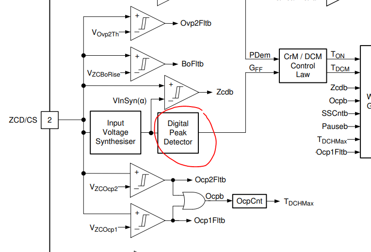
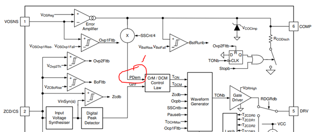
 since the Vin is synthesized instead of being directly sensed by this IC,

1.I was wondering how does UCC28056 decide its very first duty cycle(or say on-time) before Vin(syn) being synthesized?

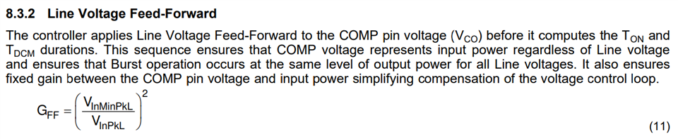
2.datasheet mentioned it use COMP to represent the input power regardless of the input voltage (ex.115 or 230)

would you elaborate on this too? I believe these two are connected?

  • Hello,

    Our office is closed for a US holiday today. We will get back to you on your question shortly.

    Best regards,

    Don

  • Hi Fred,

    I'm not sure I understand your first question, but from what I can tell, section 8.3.2.1 in the datasheet answers that: "Prior to the start of switching operation, at power - up or after a Burst - OFF period, the ZCD/CS pin voltage is sampled and used to select the appropriate starting GFF level". TONMAX0-7 will then be chosen based on that GFF level

    To your second question, can you please clarify your question.

    Thank you,

    Ray

  • Hi Ray,

    1.  I assume the feed-forward voltage is being compared at this peak detector, 

    before any switching, since the Vin is exactly the ZCD voltage. does that mean ZCD has to sample through out whole 60Hz cycle( or maybe half) to know the peak input voltage(ex.230V) and decide the correspond GFF?


    2. as for second question, it said before it decide the correspond  GFF, it will apply VFF to COMP voltage(Vco),

    but I don't really get what it means in the datasheet, would you elaborate why does it apply VFF to Vco?

  • Hi Fred,

    Thank you for clarification.

    Q1: The digital peak detector will need to sample anywhere from half up to the entire line cycle. It won't recognize the highest reading as being the peak until it sees a zero crossing (then it will know the previous max voltage was the peak of the just-completed cycle).

    Q2: That sentence in the datasheet is misleading due to poor wording. The line voltage feed forward is not applied to COMP, but VCO and VFF influence TON. By making the gain of the loop inversely proportional to the square of Vin cancels out the influence of the line from the loop.

    I hope this helps with your understanding. It's a complicated little part :)

    Ray

  • Hi Ray,

    thanks a lot, I know why PFC needs to integrate the square of Vin to cancel the line voltage influence.

    want to finalize this with last question.

    so you mean the Vco acutally represent the square of Vin part,

    I saw there're PDem and Gff before the the Ton/TDCM, does that mean PDem is the square Vin part you mentioned that from Vco?

  • Hi Fred,

    PDem is proportional to Vin^2 where Gff is proportional to 1/Vin^2

    Ray

  • got it , thanks Ray

  • Hi Ray.

    sorry for updating this forum again, recently customer bump into new issue, and it's the gating issue to our design-in so need to consult with you.

    1. I know GFF will be fixed at very beginning when you can directly sense Vac by ZCD/CS pin,

    but I wonder if PFC operate normally for a while, then the Vac increase from 110V to 264V,

    will the Ton/Gff change accordingly or it will be still and fixed?

    2. and since we don't have Vac pin like UCC28064A, is there a tradeoff or side effect especially when high input voltage like 264V?

    (duty cycle will be very low)

  • Hi Fred,

    1. GFF/TON will update when the input voltage changes per the VFFxRise and VFFxFall thresholds.

    2. Both PFC controllers were designed to work over the Universal voltage range of 90-264Vac. The UCC28056 uses discrete levels for determining Ton (starts with Max TON for lowest VIN. As VIN increases, TON decreases to maintain same power envelope). TON for the UCC28064A is analog (does not use discrete levels) and can be shifted though selection of RTSET. However, this wouldn't result in a limitation at high Vin.

    Please describe the customer issue so I can help. You may want to consider opening an E2E on the TI INTERNAL forum so that info can be shared confidentially.

    Regards,

    Ray

  • Hi Ray,

    I'll create another internal forum later just for customer issue.

    sorry I thought feed forward voltage means the Vin has to be sense directly at the very beginning 

    (both side of inductor is Vinac)

    since once PFC starts to operate the VDS voltage will be close to Vout instead of Vinac,

    so does it means the "Vin" triggering  VFFxRise  doesn't have to be sensed directly (the real Vin),

    instead it can also accept synthesized Vin so that even PFC is already operating it can still change Ton/GFF, is that right?

    regards,

    Fred

  • Hi Fred,

    I'm hoping this will clarify the relationship between Vin, GFF and TON:

    • Vin is rectified by the bridge.
    • Vrec is the average rectified voltage over a line cycle.
    • Due to Volt-second balance across the inductor, Vrec = average voltage at MOSFET drain.
    • The line voltage information is obtained by filtering this drain voltage with a low-pass filter. Thus, VinSyn(a) is a divided signal of the rectified voltage. with a small phase shift due to the filter.
    • VinSyn(a) is fed into a peak detector and that information is used to calculate GFF.
    • GFF limits TONMAX based on Input voltage.

    Regards,

    Ray

  • Hi Ray,

    1.so I would take it as yes that GFF will change during the operation according to the Vrec if we increase the Vac rms value, right?

    2. but the difference is during startup stage, the Vinac is sense directly through inductor instead of rectifying and synthesized,

    since there's no current flow through inductor at that time, right?

  • 1. Correct.

    2. I'm not exactly sure what you mean here. I suggest you run one of the SIMPLIS models and you can see exactly what Vrec, Vout, VinSyn look like during startup. https://www.ti.com/product/UCC28056#design-tools-simulation

    Regards,

    Ray