This thread has been locked.

If you have a related question, please click the "Ask a related question" button in the top right corner. The newly created question will be automatically linked to this question.

TPS2372: Simple design with ethernet jack with built in magnetics

Part Number: TPS2372
Other Parts Discussed in Thread: TPS23758, TPS23753A

Hi

If I use an ethernet jack with built in magnetics and with PoE support.

Is there a simple reference design on how to connect it to the TPS2372? What is the minimal required external components?

Kind regards

Jens

  • Hi,

    TI US in on holiday today, we will get back to you tomorrow when we are back in office.

    Regards.

  • Hi Jens,

    Thanks for reaching out to us!

    I checked our reference designs for TPS2372/3 but seems they all have discrete PoE transformer. May I know:

    - The power rating for your design

    - If you allow, I can connect you to some ethernet jack manufacturers in email. They should have teams to look through your specific requirements or do costumed design

    Best regards,

    Diang

  • Hi Jens,

    Hope everything is going well!

    May I know if your answers for the following two questions:

    - The power rating for your design

    - If you allow, I can connect you to some ethernet jack manufacturers in email. They should have teams to look through your specific requirements or do costumed design

    Besides, if you already have a ethernet jack part, we can have a look on the datasheet.

    Best regards,

    Diang 

  • Thanks for the response Diang. 

    This is in early stage so I havent selected any components yet. Please feel free to put menin touch with ethernet jack supplier. 

    I would need a steady 100-200mA at 5 volt to drive my circuit.

    kind regards

    jens

  • Hi Jens,

    Thanks for your information!

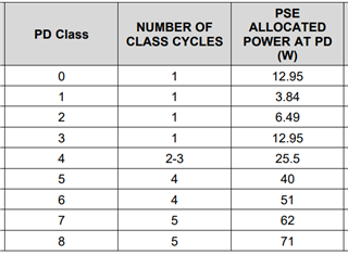
    Seems your load is about 1 W only (5 V, 100-200 mA). For cost benefit, TPS2372 is used for > 25.5 W (PD Class 5, 6, 7, 8) applications usually considering its passFET's current rating is high. 

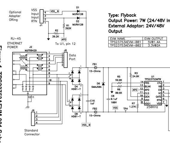
    TPS23758 could be considered for load power < 12.95 W (PD Class 0, 1, 2, 3), which has integrated PD + PWM controller + primary side FET. TPS2372 only has integrated PD. You can check the evaluation board of TPS23758  via https://www.ti.com/tool/TPS23758EVM-080, which is 5-V / 2.3-A design. Also evaluation board based on TPS23753A (www.ti.com/.../TPS23753AEVM-001) may fit your design too. It uses MJFR0429 which is an ethernet port with built in magnetics.

    Please feel free to contact us if you have any further questions. 

    Best regards,

    Diang

  • Thanks the TPS23753A look like a quite easy to use device. I checked out the evaluation board schematics and I think I understand everything to the left. Ethernet, transformer, rectifiers, and then the TPS23753APW:

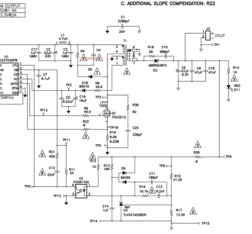
    But I think all these parts to the right of the TPS23753APW are confusing me a lot

    Trying to understand what I really need on this side, and what is just added to the evaluation board for convenience.

    From the TPS23753APW do I get some kind of voltage AC or DC from it?

    I guess maybe many of the components are there in order to handle switcing between PoE or alternative power supply. 

    What can I remove in order to make it as simple as possible and just get power from PoE ?

    Kind regards

    Jens

  • Hi Jens,

    Thanks for your reply.

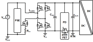
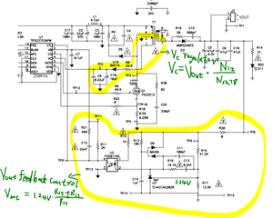
    TPS23753A itself is a power device interface (with built in passFET) + PWM controller + VC regulator. When the passFET is turned on, you will get a DC voltage at VDD-RTN (37 - 57 V in the standard). Then the downstream circuit is usually a DC/DC converter to get an isolated, regulated, and lower voltage at Vout.  

    You are correct that there is an auxiliary power supply utilizing the transformer T1's winding 1&2. Which is for generating a 9 - 19 V regulated voltage at VC for gate driving and other voltage rails (e.g. the 5.1-A VB used for feedback control). It is necessary to make the PWM controller work. 

    Then, there us a feedback control loop using error amplifier at the bottom.

    If you want to output 5 V, 100-200 mA with isolation, you may need to keep all the parts in the circuit (it is more common). If you do not need isolation, a bulk converter could be used (less common), which could refer to  

    2055.PSIL048E1(001)_Sch.PDF

    Best regards, 

    Diang

  • Hi Jens,

    Since we have not received your update for a relative long time. I will close this thread for now. Please feel free to open a new thread if you have any further questions. Thanks!

    Best regards,

    Diang