This thread has been locked.

If you have a related question, please click the "Ask a related question" button in the top right corner. The newly created question will be automatically linked to this question.

BQ25887: BQ25887 Schematic Check

Part Number: BQ25887

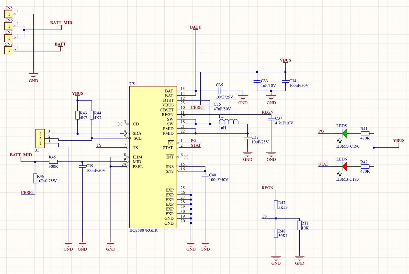
Could I get a review of the 2 cell charger schematic using the BQ25887 please?
BATT is the positive side of the 2 cell battery and BATT_MID is the middle connection between the 2 batteries. 
I do not plan on using the SNS/SYS output, so a lower capacitor was used. 

  • Hello,

    My schematic review is as follows:

    1. I see you are limiting the cell balance current to 382 mA typical. Please keep in mind maximum of 400 mA.

    2. The maximum output sink current for PG/, STAT, and INT/ is 6 mA. With a 470 Ohm Pullup with 5 V, the current when on is 10.6 mA which will damage the device. Please use the recommended 10 kOhm resistor.

    3. We recommend a minimum 44 uF capacitor on SNS as it the output of the boost converter. This is a must.

    4. I see maximum ILIM current via ILIM to GND.

    5. I see adapter source via PSEL to GND.

    Regards,

    Mike Emanuel

  • That migth explain some things with the readings via I2C. Seemed like the chip was not working okay.. Have some new chips on the way - will update per your suggestions. Heads up for anyone using the Mikroe Balancer 5 - they use 470 Ohm resistors on their PG/STAT pullups. It behaved poorly for me as well, though it kinda worked.  

  • I await your response.