Because of the holidays, TI E2E™ design support forum responses will be delayed from Dec. 25 through Jan. 2. Thank you for your patience.

This thread has been locked.

If you have a related question, please click the "Ask a related question" button in the top right corner. The newly created question will be automatically linked to this question.

LM63625-Q1: Failures of IC LM63625DQPWPRQ1

Part Number: LM63625-Q1

Hi,

I'm Smitha working at Altigreen Propulsion Labs Pvt Ltd. we are using LM63625DQPWPRQ1 in our automotive application design and we are observing that there are repeated failures of IC LM63625DQPWPRQ1 during our testing. can you please let us know what could be the reason. we have performed 

1.. output short circuit test

2. Input reverse connection test (it wont fail immediately)

but we are unable to replicate these repeated failures. request your support on this.

  • Hi Smitha,

    Thanks for using the LM63625 in your design. Can you provide the operating conditions, any available waveforms, schematic, and layout?

    Regards,

    Richard

  • please find below portion of buck converter design. Input voltage ranges from 11.2V to 14V, output 5V. please review the design and let us know. 

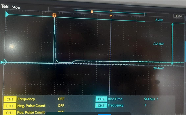
    waveform of inrush current 2.28A as shown below.

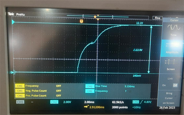
    12V input - no spikes

  • Hello Smitha, 

    Can you also provide the board layout for review?

    Thanks, 

    Denislav

  • Hi Smitha,

    In general, schematic looks ok.

    Two things I noted:

    -ceramic capacitors for VIN pin should be larger than 0.2uF. I recommend at least 4.7uF effective capacitance along with high-frequency bypass capacitors, which accounts for DC derating.
    -Not sure why there's such a big output capacitor for the buck converter. 470uF may be too large of a value. Please see application data sheet for usual values.

    Do you have any waveforms?

    Regards,

    Richard 

  • Actually we have kept 470uF at the input pin of the board so it is missed out in schematic.  Regarding the output capacitor we understand that 470uF is too large when compared with design calculated value. but does it affect the stability of IC? would that large value be the cause for IC failures?

    if you could let us know what waveforms would be needed for you to understand the failure cause, we can test and send the waveforms.

    kindly confirm if large value capacitor can affect the stability and cause IC failure so we can quickly take immediate actions for our production boards.

    Thanks,

    Smitha R

  • Hello Smitha, 

    Yes, the output capacitance can affect the stability. Also, the layout of any buck converter is very important for its proper operation.

    Can you please provide:

    1. Your board layout. 

    2. Complete schematic, including any additional input filtering.

    3. Inductor part number.

    Thanks!

    Denislav

  • Even if larger output capacitance affects stability, does it result in failure of IC? Our failure observations are : some boards have output voltage 5V shorted to ground and other boards have input 12V shorted to output 5V too. we don't think stability may cause IC failure resulting in output short or input to output short.

    Kindly confirm on this.

    Inductor part number: MSS1260-333MLB

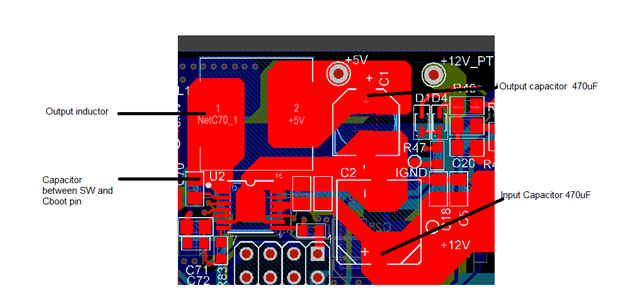
    Board layout image:

    Regarding layout - we don't have failure observations on all the production boards. We have found this failures in some of the boards only so majority of boards working but failed boards either have output 5V to ground shorted or input to output 5V shorted. we will check if we can provide layout file. Meanwhile kindly confirm if stability can affect the IC failures with shorted outputs or shorted inputs to outputs.

  • Hi Smitha,

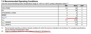
    If design is unstable enough you can violate abs max value of the device, which can lead to device damage. Additionally, in table 7.2 of the datasheet, output voltage should not fall below 0V. 

    Depending on how the tests are conducted, it is possible device can be damaged from the setup. 

    BR,

    Richard 

  • Regarding instability damaging the boards we have below queries:

    1. If that is the case, then all the boards would have got damaged. These failures are very intermittent.

    2. We observed that in another board - output voltage we are getting 9V instead of 5V. it was working properly and kept for testing for observing the failure. it was not loaded and 5V increased to 9V. when we checked for IC pins shorting to VIN or GND pins, we found that only SW pin and FB pins shorted with VIN pins. no shorts observed. 

    Can you please elaborate in detail on how instability can damage the device by reaching absolute maximum ratings. we have observed the input voltage spikes and no spikes in 12V supply. we have measured in-rush current and it is only 2.28A.

  • Hi Smitha,

    1) Can you specify how many boards have failed out of the ones tested?

    2) This is strange behavior, especially if it was normally regulating at 5V. Can you also provide the schematic. 

    I'll also assign this to the engineer in charge of E2E for this month. Please anticipate for some delay as the engineer is OOO.

    Regards,

    Richard

  • Hi Smitha,

    Can we assume the issue is resolved, because there is no update for 30  days.  You can reopen it by adding a new post.

    Thanks,

    Youhao