This thread has been locked.

If you have a related question, please click the "Ask a related question" button in the top right corner. The newly created question will be automatically linked to this question.

MC34063A: MC34063 example circuit

Part Number: MC34063A
Other Parts Discussed in Thread: LM5158

Hello E2E Experts,

Good day.

I am doing a development, for which I need to use its well-known MC34063

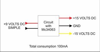
My goal is to have a balanced output of + and -15 volts from a simple 9-volt voltage from a battery.

But I can't find in your datasheet an example that works for me.

I need to implement retransformers.

The source is for portable use, with very low consumption and the space and size of the equipment where the source goes are very small. It's all SMD. 

I am attaching a block diagram of what I want to obtain for a better understanding.

In testing, the Step-Up setup worked fine for me, but the Inverting Switching setup didn't work well for me. (I was trying to combine both configurations with two MC34063s to obtain a balanced output of +- 15 volts DC) It did not work.
Regards,

CSC

  • Hello Jonard,

    Thanks for reaching out to us via e2e.

    It it not possible to create a positive and a negative output voltage the way you describe.

    Also, the MC34063A is a very basic part, so if you are looking for a well-balanced symmetric output, driven by a single converter, I would propose the following:

    Use the LM5158 in a flyback topology with dual output windings.
    The fourth winding that is shown in this picture below is not necessary. As you don't need isolation, you can directly connect the positive output voltage to the feedback resistor divider.
    The LM5158 also has an integrated FET, so the solution is pretty small.

    Best regards,
    Harry

  • Hello Harry,

    Good day. 

    First of all, I don't know what the fourth winding would be.

    Secondly, I think we are misunderstanding each other. When I consult, perhaps I express myself badly, but it is not my intention to solve with a single chip. If we go back to the example of the 34063, I thought that you could tell me, how to use two of these integrated ones to obtain the + - 15 volts.

    Regards,

    CSC

  • Hello CSC,

    Sorry when I misunderstood, that a single device is not mandatory. Nevertheless, I think it would be the better solution to use a single controller.


    Maybe have a look at our reference designs:

    https://www.ti.com/tool/PMP22992 
    https://www.ti.com/tool/PMP10733 
    https://www.ti.com/tool/PMP10090 

    Best regards,

    Harry

  • Hello CSC

    We have not seen an update from you for two weeks, so I assume the questions are answered and the issue is solved.
    I close this thread now. If there is still something open, please reply and the thread will get opened again.
    If you have any other question or of the thread has been locked, please open a new one.

    Clicking the Resolved Button also helps us to maintain this forum.

    Best regards,
    Harry

  • Hello Harry,

    Good day.

    I guess there is a little misunderstanding. I can see that MC34063A is capable of an inverting output of -12V.

    I believe the customer is looking for a possibility that this part could output -15V at 9V input from a battery.

    He can use 2 MC34063A for a +15V and the other is -15V output. The question is how. Is there any application for the such a use case?

    Thank you for the assistance.

    Regards,

    CSC

  • Hi CSC,

    Thanks for the update.
    If customer wants to use two MC34063A device, they would need to make two circuits, one for the +15V output and one for the -15V output.
    This is indeed possible and they can still supply the two devices with the same input voltage of 9V.

    The downside of this splitting is, that the two devices need to be seen as two completely separate circuits, that will switch and regulate independent from each other, as their clocks cannot be synched.

    Best regards,
    Niklas