This thread has been locked.

If you have a related question, please click the "Ask a related question" button in the top right corner. The newly created question will be automatically linked to this question.

BQ76200: Pre discharge- use power FET instead of resistor

Part Number: BQ76200
Other Parts Discussed in Thread: BQ78350, , BQ76940, BQ34Z100-R2

Hi there,

We are designing a battery pack using BQ78350 + BQ76940 + BQ76200.

The output of the battery is connected to a motor controller, with bulk capacitance of 500uF.

Originally, I planned to use a power resistor with the pre discharge function of the BQ78350.

However, we need the caps to be charged in < 100ms.

I calculated the required resistor to charge in < 100ms, and landed on 32 ohm.

Our battery is max 60V.

The resistor power would be 112.5W peak and the charge would last for 100ms.

A few problems I see with this approach- the resistor with this pulse power rating large. The second is in the event of a short circuit, I see the min time to enable pre discharge for on the BQ78350 R2 is 1 sec. This means that the pre discharge will turn on into a short and burn this power (> 100W) for 1 second.

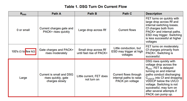
I had an idea for an alternate approach- adding a capacitor to the gate of the discharge FET.

I modeled the BQ76200 gate drive as a voltage source of 12V with 3.5k series resistor (ON) and 1.5k series resistor (OFF) from gate to source.

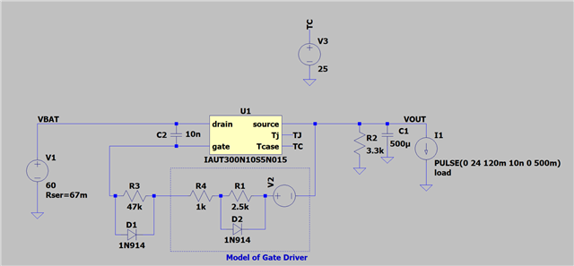
I was checking the junction temperature of the FET in SPICE and it does not appear to get too hot with this approach.

Wanted to ask

a. Do you see any potential problems with this approach

b. Could you provide the min and max ON and OFF gate driver resistance of the BQ76200 if you have it, and given this is an accurate way to model the gate driver

Thanks!

  • Hello Cameron,

    a. Do you see any potential problems with this approach
    Just to confirm, you are essentially just increasing the turn-on speed of the FET by adding additional capacitance right? It could work, but it would mean that you're also slowing the switching speed of the DSG FET. If turn-on is too slow and you have an active load when attempting to turn-on the FET, it could blow up the FET due to the amount of current drawn while the FET is in its resistive stage. If you believe this should not be an issue and have simulated the load, it may be okay.

    Something we see customers do when they need to handle higher currents through the PDSG is to parallel many high-wattage resistors in order to dissipate the power through the resistors. 

    b. Could you provide the min and max ON and OFF gate driver resistance of the BQ76200 if you have it, and given this is an accurate way to model the gate driver.
    This may provide some rough idea but likely won't be too accurate as the gate voltage is generated by a charge-pump, which is limited in the amount of current it can deliver at once. Unfortunately we do not have a way to model the driver and we do not have the min/max for the ON/OFF gate resistance. There is discussions on the driver and charge-pump in Section 2 Device Architecture of the Beyond the Simple Application Schematic application note.

    Best Regards,

    Luis Hernandez Salomon

  • Hi Luis,

    Thanks for the reply.

    That's correct, the load will not draw current at startup.

    Got it about the parallel resistors. One concern I have is having the power resistors get "stuck on" in a short.

    I wanted to ask if the BQ78350-R2 will check if there is a short circuit after enabling the PDSG FET. AKA- will it be held on for the pre discharge time even if the output is shorted?

    Thanks!

  • Hello Cameron,

    What about during protection conditions? If there's a fault that cuts the battery and then it cuts back on, is the device still ensured to not draw current at this stage? If not and you've characterized it, it should be fine.

    I wanted to ask if the BQ78350-R2 will check if there is a short circuit after enabling the PDSG FET. AKA- will it be held on for the pre discharge time even if the output is shorted?
    If there is a short, the device will detect it (as long as the current is above the SCD threshold) and disable the PDSG FET. This is mentioned in the last paragraph of Section 3.1 PRE-DISCHARGE Mode in the bq78350-R2 TRM Addendum. So it should not be stuck during a short.

    Best Regards,

    Luis Hernandez Salomon

  • Got it about the load, we will check that.

    OK- that makes sense about the short circuit threshold. One issue I do see with that is the short circuit current for our application is 40A. We are trying to limit peak inrush to < 7A. So the resistor selected to limit current into the caps for 7A will not trigger that short (the short circuit current would be limited through the resistor). I believe the minimum time pre discharge is enabled for is 1 second. Spec'ing a resistor rated to this power level which can survive a short for 1 second is not possible (we are size limited).

    I have one more question- I found this in the app note for the BQ76200. https://www.ti.com/lit/an/slua794/slua794.pdf?ts=1677179036707 

    In my simulation, the only way to allow for slow ramp yet still fast enough turn off is to use a combo of high value resistor (47k) and cap (10n) (see schematic attached earlier).

    It points out a rgate resistor > several k will prevent FET turn on.

    Is that true in this case, or is there a way to prevent that from happening.

  • Hello Cameron,

    Hmm yes that may be troublesome then, as the minimum time you could do is 1 second with this device unfortunately. I do not have an easy solution for you. Another option would be to implement the PDSG FET by controlling it with a N-Channel FET and an external MCU. This would allow some more customization with the ON time.

    I am not sure if you've looked into our newest monitor, the BQ769x2 family, which can do up-to 16s monitoring/protection and offers pre-discharge features which are much more customizable than the BQ78350-R2 and has integrated high-side FETs. The one down-side for this device is that it does not offer gauging and we do not have a companion gauge for it. If you wanted gauging with this device you'd need a top-of-stack gauge (BQ34Z100-R2)

    Thank you for pointing this out, this may be an issue I had not thought of before. It is possible if turn-on is too low for too much current to flow into the capacitor in the PACK pin, causing the charge-pump to be discharged below UVLO.

    Unfortunately the engineer who wrote this application note retired recently so I am not sure at what resistances he tested when he saw this. If you have a device on-hand you should test this to see if there's any issues. I can ask others in the team what they know if needed.

    Best Regards,

    Luis Hernandez Salomon