This thread has been locked.

If you have a related question, please click the "Ask a related question" button in the top right corner. The newly created question will be automatically linked to this question.

TPS564201: Can this Buck converted be used as a current sink, and if so how?

Part Number: TPS564201
Other Parts Discussed in Thread: TPS564208, , TPS562207

Hello,

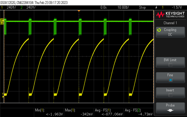
I am working with this part, TPS564201DDCR, and I've been having some difficulties with the part. Our designer has generated -12V from 12V using an inverting DC-DC controller, and then used multiples of this step-down converter, each referenced from -12V as the device's ground (pin 1) and ground as its input (pin 3), to generate a series of smaller negative voltages (-3.2, -3.7, & -6.3). I've attached an image of the switcher or the -3.7V output that we have designed.

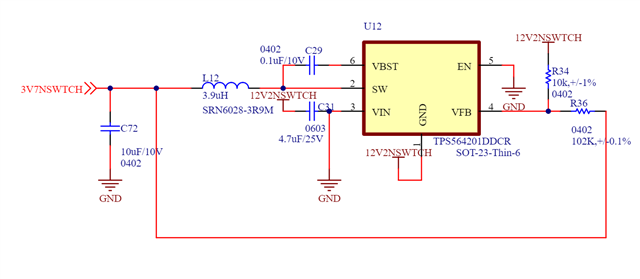
In general, we used the typical application of the device described 8.2, except we designed our gain such that we get -3.7 from -12. This generate the approximate expected voltage with the associated ripple from the having load output load attached to the device, suggesting that its possible to step-down from ground to -3.7V with this device

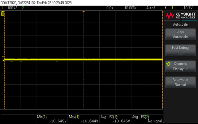
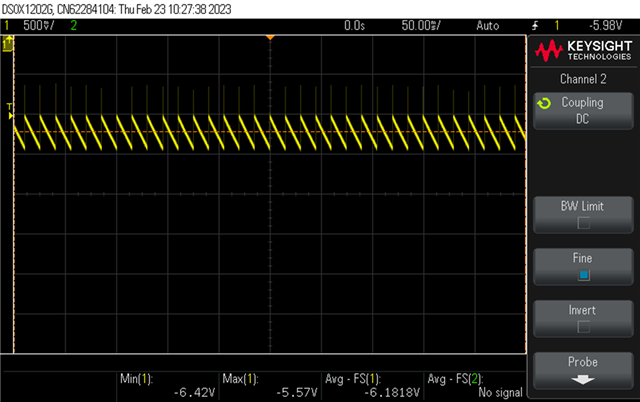
The issue with this design is that whenever a load is attached from a higher voltage than the output. The switcher rises to ground an say there, with no switching. When a load is attached to a lower voltage however, the device appears to operate as if it was a positive voltage load to ground. 
I have looked through the documentation for this device and I haven't seen anything that can allow it to act as a current sink, such that we have a load from ground to our -3.7V switcher output.
Is this design possible with this device? I have heard mixed answer from my colleagues, and I would like to know if this is possible to sink, and how it can be implemented. 

  • Hi Jason!

    1. The Vout should use 12V2NSWITCH as the zero level reference instead of GND.

    Shuai

  • Hi Shuai.
    Yes, we used the 12V2NSWITCH as our zero-level reference to calculated our resistor feedback gain for the device. That is how we achieved -3.7V from -12.2V. The real issue is not the calculation, but how to utilize this device as a current sink.


    In the first image, I've distorted the feedback pin was not-directly tied to the output and pseudo-floating; the set-up was odd and it really only proves that its possible to sink current with this device, however the feedback is what appears to distort the output when it attempts to sink.
    For what you can see, the output in yellow is on one side of the inductor, and the green is the switcher node on the other side of the inductor. When the IC begins switching, the output decreases, suggesting the device can sink the current through its bottom switching device. This is not helpful, but it does suggest that its possible to utilize these devices with a specific feedback configuration.

    I've been able to apply very small current sinks (< 1mA) from ground to the -3.7V switcher, but once the load increases significantly, the output rails to a DC values such as -10V, seen in the next image. 


    The last image is actually our -6.7V output without load, but that calculation for that is the same as the -3.7V output, and it has the same fundamental problems. Without load, the device achieves what I would like. We can also apply loads from the negative voltage outputs to lower negative voltages, causing the device to source current as expected.

    Any help in determine how to enable these devices to sink current would be very helpful. I believe its a feedback issue, but I'm unsure how to fix it.


  • Hi JJulie,

    My colleague will give you reply soon!

    BRs

    Zixu

  • Hi JJulie!

    Sorry for late. What I want to say is that if you use 12V2NSWITCH as the zero level reference, the C72 should connected between 3V7 and 12V2NSWITCH.

    Shuai

  • And for another hand, this device is ECO mode device, which has zero detection of inductor current, can't support inductor negative current. TPS564208 is FCCM mode, which can sink current in a certain range.

    Shuai

  • Thanks Shuai, I'll  try changing the polarity of the capacitor. I've ordered some sample of the TPS562207 which has a smaller layout than TPS564201 and the TPS564208. Where in the data sheet does the TPS564208 suggest it is FCCM? I see one line mentioning the mode, but as explict as the TPS562007's datasheet. 

  • continuous condcuting mode is equal FCCM mode.