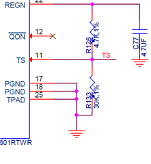
We are currently using the battery charger IC BQ25601RTWR in our design that is used to control the charging and discharging of a 1500mA Lithium ion battery.
we wanted to control the temperature at which the charging is cutoff from 5degC to 50degC but the datasheet only provides the range details from 0degC to 60degC.
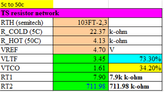
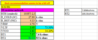
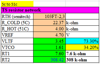
the TS pin resistor divider calculations where done for 5degC to 50degC we got the resistor values as 4.7K and 30k
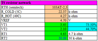
the values for the calculation have been taken are as follows.
VREGN=4.7V
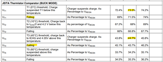
VT1-73.3% of VREGN
T1 (0°C) threshold, Charge suspended T1 below this temperature. Charger suspends charge. As Percentage to VREGN
VT3- 44.7% of VREGN
T3 (45°C) threshold, charge back to ICHG and 4.05V above this temperature. Charger suspends charge. As Percentage to VREGN
BATTERY DETAILS
RTCOLD(5C)- 22.37
RTHOT(50C)- 4.27
RT1-4.7K (APPROXIMATE VALUE)
RT2-30K (APPROXIMATE VALUE)
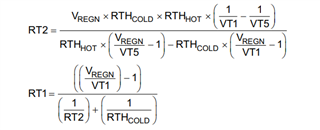
CALCULATIONS DONE:-
are the above values correct for this calculations of setting the charging temperature range from 5degC to 50degC or have we missed anything?
Also wanted to clarify some value details in the below table.
1)is the below table a standard that we have to follow or will the values vary for different temperature.
2)what does falling in the second column mean?
3)to change to 5degC to 50degC from 0degC to 60degC what are the percentage values that have to be used.
4)what does VT3 state mean for the battery(whether it will charge till the voltage is upto 4.05 and later stop charging or will the charging cutoff when it reaches the temperature,independent of the voltage ?)
PLEASE CONFIRM THE CACUALTION VALUES AND SUGGEST IF ANY CHANGES.