This thread has been locked.

If you have a related question, please click the "Ask a related question" button in the top right corner. The newly created question will be automatically linked to this question.

LM5121: Low side FET and disconnect FET failing

Part Number: LM5121

Hello,

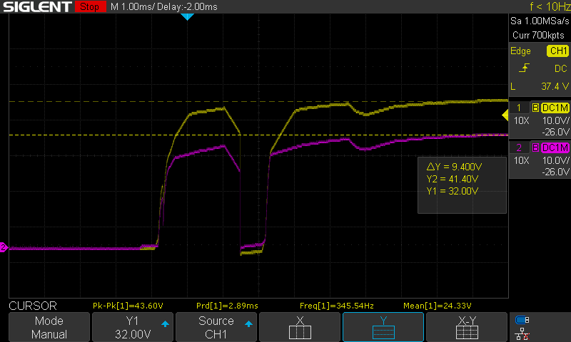
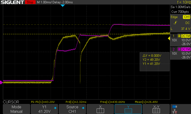
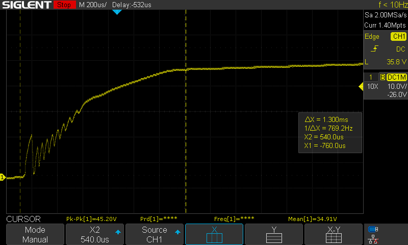
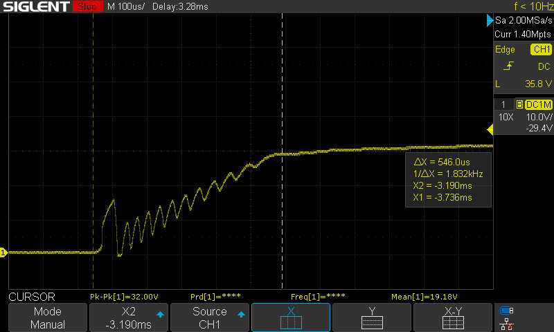
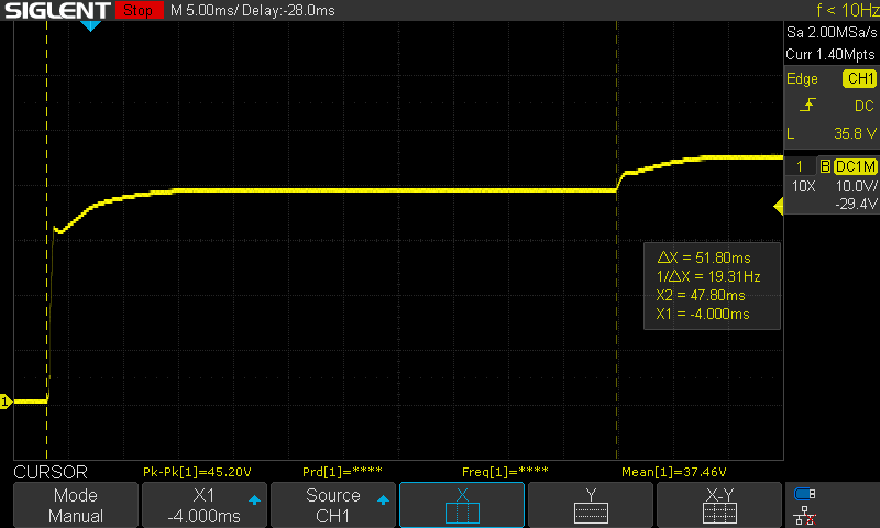
I have an issue where the low side FET and the disconnect FET are occasionally failing short circuit on startup of the regulator.

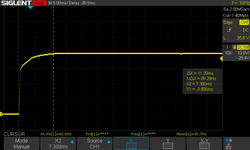
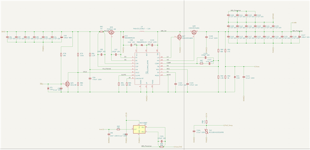
My circuit consists of the standard application schematic LM5121 configured for ~48V output voltage stepping up from a voltage range of 25V-42V.

The regulator is enabled/disabled through the use of a logic level FET that pulls the UVLO pin to ground.

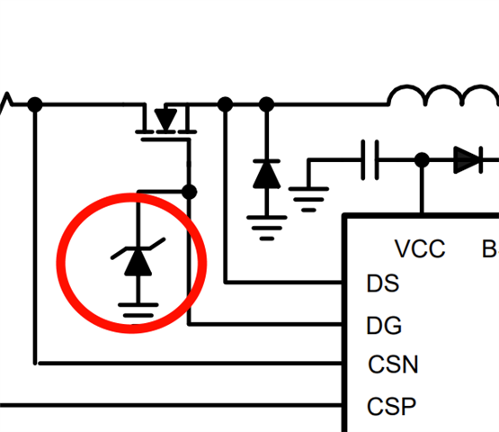
The disconnect FET used is the PXN012-60QL, and the switching FETs are ISC230N10NM6ATMA1.

The purpose of this regulator is to power a stepper motor driver and power a PoE switch, with what I estimate is an additional ~300uF of extra load capacitance on top of what is shown in the schematic attached.

The stepper driver does not immediately start on power up, so the load on the output should be mostly passive.

Any help is appreciated.

Thanks,

K

Edit:

Adding the local relevant layout where the regulator is. The net VMOTOR is the output rail.

  • Hi Keshav,

    Thanks for using the e2e forum.

    Can you give more details on the failure itself?
    From what I understand, there is a short path from Vin to GND when both low side FET and disconnect FET are closed for a long period, so the inductor saturates. Is this the case you are describing?
    I would be interested if there is no switching happening even though the device should have turned on.

    Can you share a waveform of the input current/voltage and the gate voltage during start-up, so I can have a closer look on what exactly is happening?

    You also mentioned there is no active load during start-up, but can you still tell me the output power requirements during operation?

    Thank you and best regards,
    Niklas

  • Hi Niklas,

    Thanks for your reply.

    That's correct, the failure seems to occur on startup.

    Visually it seems as though the disconnect FET fails first, followed by the failure of the low side FET once I enable the regulator resulting in a short circuit from the input supply to ground.

    My expected power output is 48V at 6A normally.

    It is difficult to try and replicate the issue as it seems to happen rarely and always results in the input supply being unable to be turned on due to an active short circuit.

    Also in the midst of debugging I tried to bypass the disconnect FET and added a 100pF capacitor between DG and DS. And upon turn on of the input supply the LM5121 started getting hot and wouldn't switch after enabling.

    Attached is the gate voltage of a working regulator's disconnect FET vs DS and the output voltage with an input of 32V upon enable. Yellow trace is DG.

    The failed regulator I have has a shorted disconnect FET but the lowside FET is still fine.

    The regulator itself gets quite hot and does not switch.

    UVLO is shorted to ground along with DG being constantly equal to the input voltage.

    Hope this helps.

    K

  • Hi Keshav,

    Thanks for the additional details.
    I checked the ratings of the FETs and the inductor, but it does not seem like any max ratings are exceeded at the FETs during normal operation and also the inductor should not reach saturation.

    It is also interesting that the failure only occurs occasionally.
    How you describe the damaged regulator, it might also be related to and ESD issue.
    Could there be a chance the device got already damaged when connecting the board, or did the failures occur in the middle of a test series?

    I will also get in touch with other team members on this case, to get additional insights.
    I will give you an update by the end of this week.

    Best regards,
    Niklas

  • Hi Niklas,

    Thanks for your help.

    I have some further information that might help.

    The problem occurs more frequently at higher input voltages ~40V.

    During the pick and place process I had to substitute the RB068MM100 with another equivalently rated Schottky diode called the  DS210W. (Datasheet linked).

    I discovered an issue with the PoE switch this is powering with it being plugged into another passive lower voltage (~17V) PoE injector port. But I would have thought the LM5121 would detect the output overcurrent and handle it.

    I do have one further question. Is it possible to modify this design to remove the disconnect FET. I have attempted to short over the FET and populate the 100pF capacitor. But this results in immediate destruction of the LM5121.

    I have another set of modified boards with added transient protection according to the datasheet on the DG pin. Replaced the disconnect FET with a higher rated one with better SOA and replaced the flyback diode before the inductor with a higher rated schottky. I'll let you know if that version is more reliable.

    Attached are some additional waveforms during testing of the regulator on the times it worked with the input current sense resistor replaced with a 7mOhm at 40V input voltage. I also replaced the DS210W with RB068MM100s as a further test.

    So far this one hasn't failed after >10 enables with no load, I'll edit my reply if it fails.

    DG pin start up:

    DS pin full start up:

    DS pin zoomed in on inrush limiting:

    Output voltage on startup:

    I hope this helps.

    Thanks,

    K

  • Hi Keshav,

    Thanks for the additional information.
    I will forward the details and give you an update by tomorrow.

    I am not sure if it is possible to simply short the disconnect FET. But I will get feedback on this question as well.

    Best regards,
    Niklas

  • Hi Keshav,

    I am still waiting for feedback on this issue.
    Please give me a little more time until earlier next week to get back to you.

    Thank you very much for your patience.
    Best regards,
    Niklas

  • Hi Keshav,

    I have some new insights on this case.

    1: Bypass of disconnect FET:
    A possible reason why disconnect FET failed with a cap from DG to DS could come from the driver, who cannot support the artificially increase gs capacitance. Meaning the FET gets too slow.
    In theory it should be possible to bypass the FET, but you have to pay special attention to the DS pin, as having the Vin signal at this pin directly could lead to errors. Therefore an additional resistor at the DS pin might be required.

    2: Low side FET stays closed/conducting:
    To make sure the low side FET does not stay closed unintentionally, it is a common approach to add an additional pulldown resistor of e.g. 10kOhm from LO to GND around the FET. This way the FET does not stay close if there is no signal at the LO pin.

    3: Lower voltage at output:
    You mentioned there might be a lower voltage of 17V injected somewhere at the output of the LM5121.
    If this is actually the case, it might explain a large inrush current if the output of the boost is pulled down by a voltage below the Vin supply.
    The disconnect pin might have broken because of this overcurrent.

    For now, I would recommend to stay with the larger sense resistor, as it seems to fix the issue, and check with some measurements if there actually have been high inrush currents due to the 17V injector port.

    Best regards,
    Niklas

  • Hi Niklas,

    Thanks for all your help.

    I did some additional testing during this period, while the device lasted for much longer. It still did eventually fail.

    But I have identified a possible cause now. When I was initially performing my testing. My device was in isolation with only the LM5121's load connected.

    However there is another motor driver with very high capacitance that is supposed to be powered in parallel to the LM5121 that was disconnected during this testing.

    Once I connected the motor driver and attempted to power it up. The LM5121 failed again.

    I think that possibly the extra input capacitance is providing a lower inductance path than my benchtop supply to add to the inrush through the LM5121's disconnect FET causing it to fail. 

    I'll see if the new revision with a better SOA disconnect FET will fix the issue. Otherwise I'll bypass the disconnect FET entirely using your suggestions and also add a 10k pulldown on LO in the next revision.

    Also is there a way to protect the disconnect pin on the LM5121 if I continued to use the disconnect FET? Is the schottky diode described in the application schematics in the datasheet sufficient to do this?

    Thanks,

    K

  • Hi Keshav,

    Thanks for the update.
    Please let me know if the new revision can fix the issue.

    I am not sure if there is a elegant way to protect the disconnect FET.
    Another idea I could think of is increasing the softstart time even further.
    This way the current inrush is limited for a longer period of time until the large output capacitance is charged.

    Best regards,
    Niklas

  • Hi Niklas,

    Does increasing the capacitor at the soft start pin also increase the soft start time of the disconnect FET?

    The datasheet seems to suggest it only affects the gain of the error amplifier after the device begins switching.

    Thanks,

    K

  • Hi Keshav,

    Yes, the softstart mostly affect the duty cycle during startup and should protect the device from large inrush currents.
    But like you already mentioned, I am not fully sure if this has a positive impact on the disconnect FET.

    Best regards,
    Niklas

  • Hi Keshav,

    As there were no further comments, I will close this thread for now.
    If you have additional questions, please reply below to re-open the thread.

    Otherwise, feel free to click on the resolved button.

    Thank you and best regards,
    Niklas

  • Hi Niklas,

    The new revision has arrived, but I have yet to test it for long durations.

    So far the upgraded disconnect FET hasn't failed after several enables. Even with the motor driver's capacitance added to the input capacitance and input voltages as high as 42V along with a load on the PoE output.

    If it fails again, I'll just cut the DS trace and solder a 500k to ground as shown in the datasheet to allow bypassing of the disconnect FET as I have an upstream hotswap controller to do that in this board.

    Once again, thanks for all your help.

    K