This thread has been locked.

If you have a related question, please click the "Ask a related question" button in the top right corner. The newly created question will be automatically linked to this question.

TPS54540: Start Up sequence for Switching Frequency

Part Number: TPS54540

Hi All,

I tried to measure the switching frequency for IC TPS54540 , we get the normal frequency at 2MHz in the operating condition 


But when I try to measure the start up sequence of Switching frequency with the Oscilloscope, the switching frequency is not 2 MHz, even if I set the time to 5s. I cannot get 2Mhz.

I would like to know what causes the frequency to not be 2Mhz when the power is turned on. Is this condition normal?

Looking forward to your reply,

Thank you

  • Hi Ully,

    I'd like to see what conditions you are operating the converter in, such as VIN, VOUT, load current information for each scope shot you are sending.  Please also send your schematic and elaborate on what conditions are in your start up sequence. Off the top of my head I know the converter switches at a pulse skipping waveform with lots of ringing at light loads, but this might be different than that.

    Regards,

    Henry

  • Hi Henry

    Thanks for your reply,

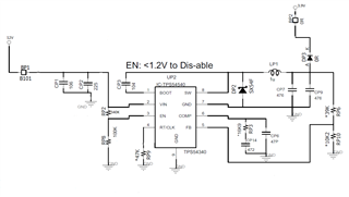
    Attached is our schematic

    And these are the conditions we use: 

    VIN : 12V

    VOUT : 3.9V

    IOUT : 1.4A

    Thank you.

  • Hi Ully,

    Thank you for your patience. I'd also suggest filling out the attached spreadsheet with your parameters. Can you also explain to me chronologically what voltages you bring your pins in this start up sequence? To clarify your device functions normally in steady state operation with the parameters: VIN = 12V, VOUT = 3.9V, IOUT = 1.4A

    Regards,

    Henry

    2703.TPS54360-361FAMILY_CALC_TOOL_REVE.xls

  • Hi Henry,

    Attached is the parameters that I have input, please check it.

    For this measurement I set the PSU at 12 V to the Power simulation board, then the power simulation board was connected to the DUT (test board). 

    actually the frequency is normal when on the operating condition. 

    2703.TPS54360-361FAMILY_CALC_TOOL_REVE_Edit.xls

  • Hi Ully,

    Thanks for filling out the quickstart calculator. If your regulator is still outputting the correct VOUT during this non-2MHz operation it could be that your converter is on the margin of pulse-skipping mode and regular switching operation. Try decreasing your switching frequency to about 1.5MHz and see if this behavior is still existing. This is because you might be failing the FSW skip requirement in the datasheet equation 9. You should also check your inductor saturation current to see if the inductor remains under the maximum 20% derated value. (Peak IL at 1.5MHz should be around 3A according to the calculator)

    Regards,

    Henry

  • Hi Henry,

    Thank you so much, I will check our frequency first, 

    I will let you know the result.