


The TPS2482PWR in my circuit isn't functioning as typically expected when enabling the chip after the load and the supply power Vin are applied. The steps I made during operational testing of the TPS2482PWR are listed below:
1.) While holding the EN pin low 0V
2.) I applied (28VDC) to Vin. The result was no power was making out to the load (125 Ohms) great.
3.) Then I drive the EN pin Hi (3VDC) and the TPS2482PWR fails to drive enough voltage to Vgate (9VDC) where I typically expect (42VDC) and this results in 5VDC of the 28VDC making it out to the load.
But if I,
1.) Leave the load disconnected from the FET's Output,
2.) Apply 28VDC to Vin and
3.) Then drivie the EN pin Hi the TPS2482PWR drives 42VDC out to the FET and fully activates it.
3.) I then can apply the 125Ohm load and see the full 28VDC being driven out to the load and 42VDC being driven to the FET.
This behavior where I have to enable the TPS2482PWR before attaching the load isn't what I should typically expect right?
If there is any insight into possible causes of this behavior or techniques to correct it I would greatly appreciate the advice.
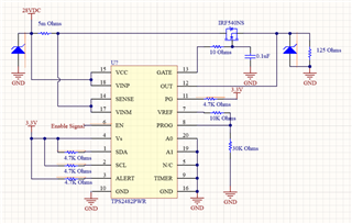
My schematic:
Very Respectfully,
-Chris

