This thread has been locked.

If you have a related question, please click the "Ask a related question" button in the top right corner. The newly created question will be automatically linked to this question.

TPS62933EVM: TPS62933EVM - Transient

Part Number: TPS62933EVM
Other Parts Discussed in Thread: TPS62933

Hi Expert,

Good day.

The customer needs your expertise. Please advise.

my name is Raffaele Salvati, a Ph.D. student at the University of Perugia. I am working on a WPT system for industrial equipment for dynamic applications and currently using your TPS62933EVM as DC/DC Converter module.

 Due to the application scenario, we cannot transfer power continuously, therefore we decided to use supercapacitors as storing devices after the DC/DC (due to their low voltage rating). The system is able to charge the capacitors and supply the load with 5 V but using an Arduino to monitor the supply voltage I found out that there are several spikes of about 1 V..  I think its due to the transient response of the DC/DC and tried to fix it adding the feedback capacitor but I encountered a few obstacles.

First of all, I don't know how to define the output current since the load (parallel of supercapacitors and an Arduino board) varies depending on the capacitors' charge status. However, assuming a Resr of the output capacitor close to 0, I calculated that using C0 = 2.5 F the minimum feedback capacitance is 390 uF ("Stability Analysis and Design of Internally-Compensated Peak Current Mode TPS62933 - Part II: How to Select the Feedforward Capacitor", Eq. 18).

 I will try this configuration next Monday, do you think this could solve the problem or there is something better I can do?

Keep safe


Regards,

Josel

  • Hi Josel

    I would like to check some details here:

    1. Did you use the default setting of the EVM board? If you have change the spec, would you please share me your schematic?

    2. If it is possible, would you please capture some waveforms include, input voltage, SW voltage, inductor current, output voltage and load current?

    You could send me email for detailed discussion: ruby-li@ti.com

    Hope this helps.

    BRs

    Ruby

  • Hi Ruby,

    Good day.

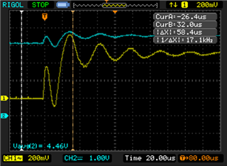
    I have used the default setting of the EVM. This morning I tried for the first time to add the feedback capacitor, which was not placed, but it got worst. I am sending you the output voltage measurement with no feedback capacitor and with capacitor Cff = 69 nF. The blue trace is DC coupled whilst the yellow one is AC. As input voltage, I switched on and off the output line of a DC power supply (9 V).

    Unfortunately, I do not have current probes but can try measuring the voltage across a low-value resistor in series.

    The load resistance in parallel with the supercapacitors is an 82 Ohm resistor, it emulates the current consumption of the Arduino board which is about 60 mA at 5 V.


    Please advise.

    Regards,

    Josel

  • Hi Josel

    Would you mind sending me email since I am on customer visit and may have a delay here. 

    When using the EVM, is there any output without any loading?

    When using a resistor as the load, is it a power resistor?

    Hope this helps.

    BRs

    Ruby

  • Hi Josel

    Would you mind sending me email since I am on customer visit and may have a delay here. 

    When using the EVM, is there any output without any loading?

    When using a resistor as the load, is it a power resistor?

    Hope this helps.

    BRs

    Ruby

  • Hi Ruby,

    I also emailed you.

    What do you mean by "any output without any loading"? The EVM's output is connected to an RC load, two series supercapacitors (5 F, 3 V each) in parallel with a 1/2 W 82 Ohm resistor.

    Please advise.

    Regards,

    Josel

  • Hi Joselito,

    My colleague will check it and give you reply later!

    BRs

    Zixu

  • Hi Joselito

    I mean that customer could use the EVM with only a DC input supply, and do not connect it to any loading (Eload nor resistor) first so that they could check whether the EVM has any issue.

    Then, if possible, is there an eload in the lab? please use that to do the test.

    Make sure the resistor is a power resistor which could transfer power. Not use a 0603 package nor 0805 package resistor, it could not transfer power.

    Hope this help.

    Any question, please let me know.

    Thanks.

    BRs

    Ruby

  • Hi Joselito

    If I am not wrong, customer could not get the target output with a large output cap? Would you please do me a favor to check the value of the output cap?

    We may have a limit of the output cap value, it is mainly limited by OC limit and soft start time. I would like to check the scenario detaily

    Thanks.

    BRs

    Ruby

  • Hi Ruby,

    Good day.

    Unfortunately, we don't have an eload. Instead, I used through-hole resistors, not SMD. Nevertheless, I would like to clarify my objective.

    The EVM is functioning perfectly, and I can attain the desired output voltage with the default module (with Cout = 44 uF). However, the module's input voltage is a square wave with 10% DT. The problem I'm encountering is sharp spikes on the output voltage associated with the input voltage's rising and falling edges (refer to the attached file). This issue does not occur when using a constant voltage as input.

    I have attached the transient response of the default setting and my attempt to place the feedback capacitor in previous emails. The application's load is an 80 Ohm resistor (equivalent resistance of the MCU board) parallel to a 2.5 F supercapacitor.

    I hope this clarifies the situation.

    Please advise.

    Regards,

    Josel

  • Hi Joselito,

    My colleague is on leave and reply will be given once she comes back to office!

    BRs

    Zixu

  • Hi Josel

    Thanks for your detailed clarification, did you attach a file in your last response? I could not find any attachment.

    If I am not wrong, your application works under line transient (Vin is a pulse ), and what is the frequency of the input? Where does it come from? We could add input cap to reduce the input transient slew rate and thus reduce the output transient over shoot.

    2.5F is not suitable for this application for mainly two reasons:1. the soft start time, 2.5F is too large for the device to charge to the target voltage during the soft start time, once the output voltage could not reach 65%target when soft start ends, the device would work under UVP condition. 2. the stability, the device could not get a stable performance when the output cap is too large since the bandwidth would be too small, and the internal compensation would not work properly since it is fixed.

    I would recommend that:

    1. Add input cap

    2. Add output cap not over mF

    3. Increase switching frequency

    4. Add Cff not over uF

    5. Decrease the inductor value considering the current ratio 0.2 (ripple VS 3A)

    6. Add the soft start cap when you increase the output cap

    Hope this helps.

    BRs

    Ruby

  • Hi Ruby,

    Good day.


    Here is the attachment>

    Regards,

    Josel

  • Hi Ruby,

    Good day.

    the EVM is used as voltage regulator for a WPT system.. The input voltage is provided by a full-wave rectifier with a smoothing capacitor of 330 uF, which means there is already a capacitor at the input of the DC/DC module. In my application, the coils of the WPT system align periodically at a frequency of about 3/4 Hz, and power can be transmitted for a small interval of the period. Therefore, I need a large capacitor at the output to act as a battery.

    I do not believe there are any soft start or stability issues. I can charge the supercapacitor up to 5 V and keep the voltage stable around 4.9 V (please refer to the previous attachment). However, the problem lies in the several spikes that occur at the rising and falling edges of the input voltage.

    As per your suggestion in the previous response, I will try to implement the required changes and keep you updated on the progress.

    Regards,

    Josel

  • Hi Josel

    Thanks for the clarification, will wait for the feedback on your next test result.

    BRs

    Ruby

  • Hi,

    The customer responded.

    I'm glad to inform you that the system is now working properly. The only modification I made was to replace the input capacitor with two polymer capacitors of 150 uF in parallel, instead of the previous electrolytic capacitor of 330 uF. I performed some tests this morning and found that the amplitude of the spikes has reduced to less than 200 mV, which is a significant improvement from the previous readings that were as high as 800 mV.

    Thank you for your assistance in this matter!

    Best regards,
    Raffaele
  • Hi Josel

    Thanks for the feedback, then I will close the post.

    BRs

    Ruby