Other Parts Discussed in Thread: PSPICE-FOR-TI
Hello, ucc28c45 pspice lib model is not functioning in my LTspice. Nothing is working, not even the oscillator. I can usually import models in this way from TI. Please help, thank you
This thread has been locked.
If you have a related question, please click the "Ask a related question" button in the top right corner. The newly created question will be automatically linked to this question.
Hello, ucc28c45 pspice lib model is not functioning in my LTspice. Nothing is working, not even the oscillator. I can usually import models in this way from TI. Please help, thank you
Hi Bill,
Exactly what is the error you are receiving? Does the model start, but crash. Does the model not simulate at all?
Eric
Hi Eric
Please see attaches. The simulation runs till vdd exceeds the uv, then an internal terraHz oscillation begins. This is visible in Idd. The simulation proceeds very slowly. I simplified the circuit a lot. The log file indicates the subcircuit has V3 undefined so it set to zero. Sure looks like the subcircuit has a problem. I can't figure out how to attach files,
Hi Bill,
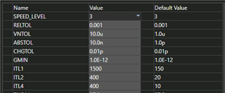
This is a switching simulation and Pspice/LTspice always have difficulty with convergence. Usually I have to loosen the default simulator tolerances (RELTOL, VNTOL, ABSTOL, etc) and, most importantly, set a maximum time step that is well below the expected switching frequency. These Spice simulators try to take large time steps and get stuck oscillating in time, as you mentioned.
Here is an example from Pspice. Notice the default values in the last column and the value I used in the second column.

For the maximum time step I used the "schedule" option. Not sure if that is available in LTSpice.

Regards,
Eric
Hi Eric,
thank you for the suggestions. They all make sense, but unfortunately the spice subcircuit model is still internally oscillating.
Hi Bill,
TI created these models with Pspice from Cadence and I've used the UCC28C4x models in (free) Pspice for TI, so I know they work. It seems there may be an incompatibility with LTspice.
Regards,
Eric
Thanks Eric, I guess I'm out of luck with the TI pspice model for UCC28C45. TI please note, it might be a good idea to fix the model. A "proper" model imports into LTspice and works.
Thanks Eric, I guess I'm out of luck with the TI pspice model for UCC28C45. TI please note, it might be a good idea to fix the model. A "proper" model imports into LTspice and works.
Hi Bill,
Can you post a screen-shot of what you're trying to simulate so I can see if it works it in Pspice-for-TI? By the way, Pspice-for-TI is a free download. You can try running the model in that simulator.
Eric
Bill,
As you know, LT is a direct competitor of TI. The "cores" of LTspice and Pspice have diverged over the years. TI does not directly support LTspice.
Eric
I stupidly assumed there was some uniformity in spice models. Obviously not. Plenty of folks don't use pspice, so I guess they are out of luck
Hi Bill,
I'm looking at creating a UCC28C45 simulation in Pspice for TI now. Are you simulating a flyback or a boost? What are your requirements: Vin range, Vout, Iout, fsw, etc. If I can provide a working Pspice-for-TI design file would you consider using it?
Eric
Hi Eric
Thanks for your offer to help design a circuit! We have an existing circuit used in production of several products. It is a 28v/12v flyback. I'm not at liberty to change the circuit. I was just trying to figure out why the 12v output overshoots a bit on turnon. This is not a problem. I was trying to model it. At my company we must use the software tools we are given, so Pspice for TI is not an option.
Thanks again for all of your help!!
Bill
Hi Bill,
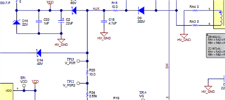
Do you have an AUX winding with PSR followed by an RC filter to the controller's VDD pin?
I found that reducing R15 from 10 ohms to 0 ohms reduced the overshoot of my recent flyback design.


Good luck,
Eric