This thread has been locked.

If you have a related question, please click the "Ask a related question" button in the top right corner. The newly created question will be automatically linked to this question.

TPS543C20: Transient PSpice Model

Part Number: TPS543C20

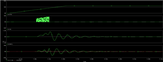
I am using the TPS543C20 PSpice model setup as a 12V to 5.1V 7A supply. When running the Startup simulation, the SW output begins switching as expected, however the current at the inductor input and VOUT oscillates for about 0.5ms before the SW pins stop switching. VOUT and inductor input continue to oscillate, settling close to 0.

I have used this model for a 5V to 3.3V 5A design with good simulation results.

Attached is the project I am having issues with. I've reviewed and consulted with colleagues on my setup/design and it looks like is should work. Am I doing something to the design or could there be something in the TPS543C20 model that could be causing this behavior? Help is appreciated.

P5V0.zip

  • Hi John

    My colleague will check it and give you a feedback early tomorrow, thanks!

    xueliang

  • Hi John,

    I was able to successfully simulate a condition of 12V to 5.1V/7A by making the following adjustments: Change RILIM to 50kOhm and change the inductor to 470nH. I believe the error you're seeing is a limitation of the PSPICE model, but I will need some more time to confirm this. I will update you here.

    Best regards,

    Britton

  • I was able to get reasonable results using the suggested values for the inductor and ILIM pin resistor. I also ran the sim with the ILIM res set to 15k, which brings the OCP closer my design, with acceptable startup results.

    If I am running into a model limitation, is there a way I able to confirm my calculations for ILIM and inductor make for a working design? Also, I would like to know as much detail about the model limitation as you can share.

    Awaiting your update. Thank you.

  • Hi John,

    After looking into this further, 2.8uH is not an acceptable inductor selection for this device because the inductor ripple current will be reduced below 10% of the maximum device current. The inductor ripple current must be sufficiently large (at least 10%) of the maximum IOUT so that the device can sense properly, in this case that is 4A. With a 2.8uH inductor, inductor ripple current is estimated to be 2.75A. If we decrease the inductor value to 1.5uH, the inductor ripple current is 5.12A, which is sufficient for this device. 1.53uH is the maximum inductor value for TPS543C20. On the lower end, 470nH also provides an acceptable solution, as it will not cause the inductor ripple current to be large enough to cause problems.  

    In regards to RILIM, 15kOhm is a great choice (15.5A). This is sufficiently high so that marginal changes on the load will not trigger the current limit.

    I also double checked the output capacitor selections for this design. In this application, the provided output capacitance was slightly too high for stability. I recommend removing 2x 100uF capacitors so that the output capacitance is dominated by 1x 220uF bulk cap and 4x 100uF ceramic capacitors. When you design your schematic, I recommend adding a feedforward capacitor to the resistor divider network as well.

    I did run this new configuration through PSPICE but a 1.5uH inductor still causes issues for the PSPICE model. It is hard to say what is causing the model to behave this way, but it seems like the inductor current is increasing too high, too early during startup and causing shutdown. That said, I have attached a detailed spreadsheet to this post covering the calculations and component selections for your application. An inductor selection of 1.5uH is acceptable.

    Best regards,

    Britton

    TPS543C20_Component_Calculations.xlsx

  • Thanks Britton. Your suggestions have helped and give an acceptable startup sim. I was able to get it to run with a 1uH inductor, but the feedforward cap was key. Thanks again.