This thread has been locked.

If you have a related question, please click the "Ask a related question" button in the top right corner. The newly created question will be automatically linked to this question.

TLC59581: Problem with LED driving for high currents

Part Number: TLC59581
Other Parts Discussed in Thread: TIDA-00161

Hi!

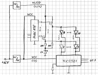
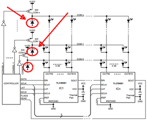
I'm developing an LED indoor display. I use matrix LED display driver type TLC59581. I use 4 drivers on one panel (connected in series).
The supply voltage of the RGB LEDs is 4.2V, and driver supply voltage is VCC = 5V (separate). I use a 4-layer PCB. My solution is very similar to TIDA-00161 ( https://www.ti.com/tool/TIDA-00161 ).
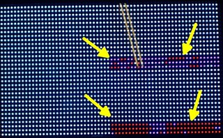
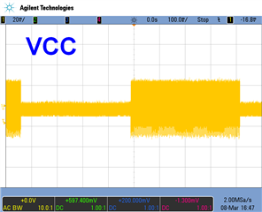
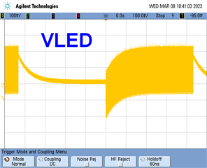
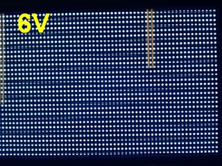
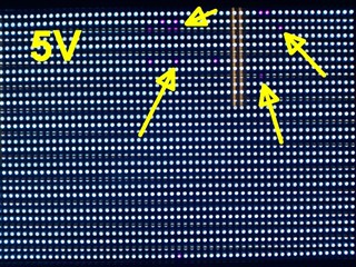
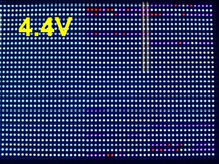
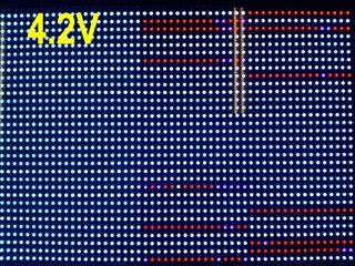
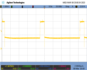
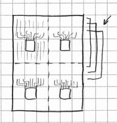
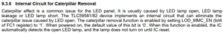
At small LED currents, everything works fine, but at high currents, some LEDs do not light up (check the picture). Iref=25mA, registers GS/BC/CC=max. The absolute maximum ratings parameters are not exceeded. VCC (5V) supply voltage checked with an oscilloscope - in no case does the voltage drop by more than 100 mV during operation.
If this problem occurs, then rewriting data and control registers doesn't help. I need to reset the power supply. Adding bulk capacitors for VCC/VLED doesn't help. LED open detection error flag is not set (read by loopback).

Where is the problem? What can I check?
Dependence on the LED current suggests it's an EMC or power supply issue. But everything seems correct...

  • Hi,

    Sorry, I'm on sick leave, I'll reply to you tomorrow.

    Thanks for your understanding!

    Best Regards,

    Ives Li

  • Some information. I send a simple block diagram and waveforms for VCC and VLED voltage (AC coupling in the oscilloscope) when I switch on/off all RGB LEDs.


    Another test. I connected VLED to an external laboratory power supply and changed the voltage from 6V to 4.2V. Decrasing value of VLED voltage causes more LEDs to light off. Important - increasing the VLED again (and send new data) does not solve the problem. I need to reset the TLC59581 supply voltage (VCC).


    I have a feeling that the problem is in the internal structure of the TLC59581. For some reason, some analog part of this IC latches and stops working. Re-uploading the data/control registers does not help. Only on/off power supply. The problem is that there are separate supply voltages VCC and VLED.

    I have another panel with red LEDs only. VCC and VLED power supply is common. There is no problem there...

    One more waveforms - the output of one of the TLC59581 chips. When the LED is on, we have >0.5V on the TLC output - it seems ok.

    Is it possible that the voltage drop across the conducting LED is too large and TLC59581 permanently disables the output?

  • Hi Adam,

    Sorry for the later reply.

    For your problem, I have some question for you:

    1.what about the forward voltage for your RGBs.

    2.Did the LEDs which is not light up is always the same one or it happened randomly.

    3.What's the value of LOD_MMC_EN bit in FC1 register and ED open detection threshold 

    4.I noticed that the unlighted LEDs only appear in right half of your panel, is there any difference between right/left  half of your panel?

    Thanks!

  • Thanks for the answer.

    1. Forward voltage @20mA (static measurement).
    R - 1.97 V
    G - 3.06 V
    B - 2.99 V

    2.
    This occurs in a similar area and yes I can say they are the same LEDs.
    Important - we have connected rows: 1 with 17, 2 with 18, etc. All rows are controlled by 16 transistors (32 rows). The 32 coloumns are connected to the TLC outputs. There are 4 x TLC59581 on one panel. During multiplexing, two rows of LEDs are light at a time.

    TLC59581 placement on the panel:

    3. Registers setting:

    FC1:
    fc1->bits.LODVTH = 0b01;
    fc1->bits.SEL_TDO = 0b11;
    fc1->bits.LOD_Removal_EN = 0b1;
    fc1->bits.RSV = 0b000;
    fc1->bits.PREC_EN = 0b0;
    fc1->bits.PREC_MODE3 = 0b0;
    fc1->bits.RSV2 = 0b000;
    fc1->bits.CUE = 0b0;
    fc1->bits.CCB = 0b100000000;
    fc1->bits.CCG = 0b100000000;
    fc1->bits.CCR = 0b100000000;
    fc1->bits.BC = 0b100;

    We have a software problem with reading data from the LOD registers. I'll let you know when we finish it.

    4. The left panel is powered from the higher voltage VLED and this problem does not occur. But high voltage causes too much heat loss...


    What is this setting?

  • Hi Adam,

    I noticed that the LEDs which cannot be turn on is green/blue LEDs, which have higher forward voltage compared to red LEDs.

    And left half didn't have this phenomenon because it has higher LED voltage.

    So, I think it may caused by the voltage drop on routing and it triggered the LOD removal function. 

    My suggestion is:

    1. Turn off LOD removal function, see if the LEDs sill cannot be turned on.

    2. If the LEDs could be turn on by LOD_Removal_EN = 0, Then change LODVTH to lower value (0b00) and enable LOD removal function again.

    Thanks!

    Ives Li

  • Hi,

    sorry for the late reply.

    Setting LOD_Removal_EN = 0 has no effect... :( No difference in operation.

    There are two problems.
    1) Too low voltage at the OUTx output. The TLC59581 needs about 0.5 V for the correct operation of the output current source. In my circuit, this voltage temporary drops to about 0.4 V, which causes incorrect operation. Adding bulk capacitors, using better MOSFETs, slightly increasing the VLED supply voltage solved the problem (+improving the PCB). Problem solved.

    2) When the LED matrix power supply (VLED) is too low, the output OUTx of the TLC59581 is permanently turned off (for a row). I understand that for too low voltage, the output current source does not work properly. But why after increasing the supply voltage (VLED), the outputs still do not work? Why is a power supply reset needed?

    Another question:
    Do you have any tips for using a Zener diode? In TIDA-00161 you use BZV55-C3V0 NXP (3V@5mA). In my circuit, for voltage <2.6V (measured on a diode Zener diode) ghosts appear. Can I use any lower voltage? Is it just power loss? E.g. simple rectifier diode with Vf=0.7V is ok?

  • Hi Adam,

    I'm out of office today,I‘ll reply you as soon as possible.

    Sorry for that and thanks for your understanding!

    Ives Li

  • Hi Adam,

    Why is a power supply reset needed?

    It is because you turn on LOD_Removal function, and LOD detection threshold default value is 0.4V. So the LEDs are disabled after detecting the open failure, even you set higher Vled it still cannot light up.

    Can I use any lower voltage? Is it just power loss? E.g., simple rectifier diode with Vf=0.7V is ok?

    Yes, you can choose lower voltage. The Zener diode is used to clamp the voltage on LED and quickly discharge each line when MOSFET is off. 

    If the Zener voltage is set too high, the upper side ghosting would not be eliminated, if the Zener voltage is set too low, the LED will stand too high reverse voltage, which may decrease the life span of LEDs.

    I will suggest setting the voltage at the 0.6*VLED.

    Thanks!

    Ives Li

  • Hi,

    Thank you for your support. Problem solved.

    Can't believe how I missed this information: