This thread has been locked.

If you have a related question, please click the "Ask a related question" button in the top right corner. The newly created question will be automatically linked to this question.

TPS543C20A: TPS543C20ARVFR can not work correct

Part Number: TPS543C20A


Hi Team,

At present, the output voltage is normal, but 5V can only increase to 7A. 3.3V can only be added to 10A.
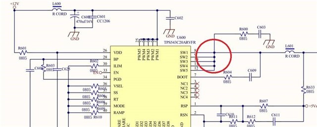
Cancel a positive and negative remote sense, RSP/RSN feedback directly adopts the PCB board.
The waveform is now hanging in SW1 ~ SW5, and the frequency is incorrect.
Please refer to it, where can we set up an exception?

  •  

    The schematics that you shared do not show component values, but the description and waveforms suggest that the control loop is not stable and is oscillating.  That oscillation is causing it to trigger a fault condition, Over Current, Over or Under voltage, when loaded.

    What tools, if any, were used to select the components, including Inductor, Output Capacitor, feedback resistor and feed-forward capacitor?

    Can you enter your design values and selected components into the TPS543C20A design tool -> https://www.ti.com/lit/zip/slurb00 so we can analyze the loop stability?

    Regarding the remote sense connections:

    How far away from inductor is the remote sense point following the power-path?

    Is there additional capacitance local to the remote sense point not shown on the current schematic?