This thread has been locked.

If you have a related question, please click the "Ask a related question" button in the top right corner. The newly created question will be automatically linked to this question.

TPS65219: Reprogramming the TPS65219

Part Number: TPS65219
Other Parts Discussed in Thread: AM623,

Currently, I am using TPS6521903 to power my AM623. Now I am studying if I am able to use the same chip to power my FPGA, PHY and other circuitry on my board. It has all the feature I need.

However, the problem I have now is that the output voltage setting of the TPS6521903 I used to power the AM623 are different than the second one I need right now for my other part of the circuit. So I cant drop it in without modification. I also want to try and avoid ordering different variant so one less internal part number to keep track of. I also don't think TI would create that config just for me(smile). So the plan is to have my microcontroller reconfigure the second PMIC, but I have a few question about doing just that. 

1. From what I understood from the datasheet, I2C command can only be serviced when it is in ACTIVE mode, which also enable the output. Is there a way for me to reconfigure the PMIC without turning on the output, to avoid the default output voltage potentially cause a problem to my circuit?

2. If it is not possible to reconfigure the chip with the output turned off, could I power VSYS up first, let it go into ACTIVE and then reconfigure the chip. After reconfiguration, switch the PVIN on with a external load switch to start the voltage regulation?

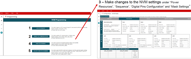
3. Will the voltage setting I reconfigured return to default setting after a reset? Is there a way I can do to make my changes permanent?

4. After reconfiguration, will this chip reset and restart its power on sequence with the new voltage setting?

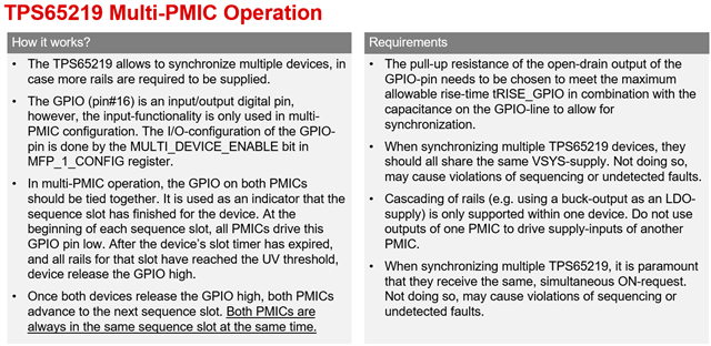
5. In the datasheet, there is a mention of using multiple TPS65219 together in "Multi-PMIC operation". But I can't find this section in the datasheet. Can TI tell me how multi-PMIC work with TPS65219? The I2C address of this PMIC can only be change using I2C, but how can I access to the two PMIC  when they all have the same address at first turn on?

That's all the question I have right now. I may have more in the future, we can either continue here or TI representative could contact me through email (preferable).

Thanks a bunch!

  • Hi,

    Thank You for using E2E! We will take a look at the information and provide an update within 24Hrs.

    Thanks,

    Brenda

  • Hi,

    Thanks for your patience! The TPS65219 PMIC can be re-programmed in Active (PMIC ON) or Initialize (PMIC OFF) states. The Active state have I2C communication enabled by default but in Initialize state there will be an additional step required to enable the I2C communication. The challenge with re-programming a pre-configured NVM (i.e TPS6521903) is that it could come with the FSD (first supply detection feature) enabled by default. This means the PMIC transitions from "no power" to Active state as soon as VSYS is connected, ignoring the state of the enable pin (EN/PB/VSENSE) during the first power-up. This makes it difficult to re-program the NVM before the device executes the power-up sequence.

    Here are the options we recommend:

    • Using the user-programmable variant/DIY which comes with all the PMIC rails disabled by default and with the FSD feature disabled as well. This variant comes in a 4x4 (TPS6521905RSMR) or 5x5 (TPS6521905RHBR) package. 

    • Re-programming the TPS6521903 variant (recommended for prototype only). In this case, since the PMIC will automatically turn-ON the rails with the default settings/output voltages, it will require the following steps: #1 sending an OFF request through I2C, #2 enabling the I2C communication in Initialize state, #3 making changes to the registers, #4 saving the changes into the NVM so they become the new default values. The Programming page of the GUI explains the process (link below).

    • Note: If the PMIC is re-programmed from the Initialize state (when all the rails are OFF), an external 3.3V must be used for the I2C pull-up resistors to communicate with the PMIC. 

    https://dev.ti.com/gallery/info/PMIC/TPS65219_GUI/

    Thanks,

    Brenda

  • Also wanted to include information for the multi-PMIC operation. This is a great feature in the TPS65219 PMIC that allows synchronizing multiple devices to power processors and SoCs that require multiple rails! Here is some information for the multi-PMIC operation, feel free to let us know if you have any questions and we will be happy to help.

    • GPIO (pin#16) is used to synchronize the two PMICs. 
    • To configure the GPIO pin for multi-PMIC, register field "MULTI_DEVICE_ENABLE" must be changed to 1.
    • The GPIOs on both PMICs should be tied together sharing the same pull-up resistor.  
    • The I2C address for the 2nd PMIC must be changed on register field "I2C_ADDRESS" so they can both be connected to the same I2C bus without conflict. 

    Thanks,

    Brenda