This thread has been locked.

If you have a related question, please click the "Ask a related question" button in the top right corner. The newly created question will be automatically linked to this question.

TPS61022: Chip failing in production release

Part Number: TPS61022

Hi,

I'm after a sanity check on an implementation. For no reason that I can see this chip sometimes fries to a dead-short.

The design uses a large super-capacitor input (very low ESR) backed up by several 22u/10V/X5R/0805 capacitors. The voltage ranges from 0-5.23V. Due to the nature of the turn-on the chip will first turn on around the 1.7v mark and then can potentially continue to the lowest on level of 0.5V. 

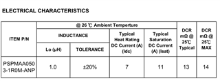
There is a 1uH inductor with a 11A/-30% saturation point.

This feeds into 4x 22uF/10V/X5R/0805 capacitors. 

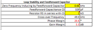
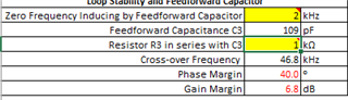
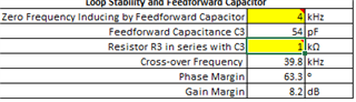
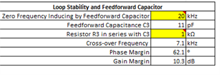
Due to a little overshoot on low current I added a 1k/330p feed-forward phase compensator. At very low current it regulates to 5.15v, then with any real load (>50mA) it regulates to 5V as expected. An oscilloscope inspection of the output showed it to be working correctly, clean (low) ripple.

The output is 5V and acts as VBUS. Technically the only current limiter is that of the TPS61022. There is a UVLO circuit on the VBUS line, if it detects less than 4.4V the VBUS output is shut-down. The UVLO is a hardware comparator driving an interrupt in a CPU so there will be a us duration delay, but it's still fast acting in the scheme of things. In the product that failed there definitely wasn't a short condition but I mention it anyhow.

The only other item of significance I have is that there was an excessive amount of heat generated which has to mean the super-capacitors were charged and then the short went through the TPS61022 at very high current. It was enough to melt the soldering on a connector! Since then VBUS is at very low resistance short, in the mOhm range


Regards,

Andrew

  • Hi Andrew,

    Thanks for providing very detailed information.

    Have you try another part? 

    the super-capacitors were charged and then the short went through the TPS61022 at very high current

    Sorry I am a little confused about this, what do you mean about that "the short went through the TPS61022 at very high current"? 

    As you said  there was an excessive amount of heat generated, maybe the chip is triggered thermal shutdown.

    Thanks.

    Regards,

    Nathan

  • The chip is toast, there is a short from output to ground, and probably from input to ground given the amount of heat that was generated. It was enough to desolder a connector on the board.

    Is the chip unstable at high output with/without phase compensation when the input voltage is low/high, that is to say should the phase compensation be switched in based on the input voltage?

    If the chip can't operate reliability across its input range this is serious position for the product.

  • Hi Andrew, 

    If you worry about the stability issue, you can use the calculation tool in ti.com to check the stability. I think there is no need to switch compensation.

    Regards,

    Nathan

  • I've tried this tool and it won't allow me to change the feed-forward capacitor.

    I'm unsure if this is the issue or whether the chip is just notoriously unreliable. I've had many short over the development period for no obvious reason. Now that it's in production, a risk I onboarded for the very good specification it offers for supercapacitor usage, I find myself in a state or worry. It's also being used in another upcoming product. The products are expensive and non-repairable, a 5% failure rate would be unacceptable.


  • Hi Andrew,

    About the calculation tool, you can change the feed-forward cap by changing "Zero Frequency Inducing by Feedforward Capacitor" item.

    What is you max output current? I think 330p feed-forward cap is large for most of application conditions. Have you tried to remove this cap or try smaller one?

    Is it possible that when there is large load current, supercap voltage reduce to a voltage lower than UVLO of TPS61022? (0.5V)

    Regards,

    Nathan

  • Hi Nathan,

    These values actually came from yourself a while back as I had voltage overshoot at low current.

    Max output is 8A, the valley current limit.

  • Hi Andrew, 

    Sorry that TPS61022 can't support 8A output current.

    The valley current limit means the inductor current, it is roughly equal to input current, not output current. (and for Boost, input current is larger than output current)

    With a large current, the output voltage will be much lower.

    Regards,

    Nathan

  • Hi Nathan,

    I'm unsure what the current limit is in pass-through mode but theoretical that is the limit I could hit in the unlikely event of a near short. Basically I need to know whether this chip has a stability problem working across its specification - 0.5v-5.25v output and 0-8A input.

    It seems I may have corrected the phase for low current only to cause instability at higher current, though this is a guess. I can't explain why the chip is otherwise so unreliable.

    Andrew


  • Hi Andrew, 

    With large load current, there is much noise at FB pin, you can add a 50ohm resistor series with feed-forward cap (R2 in your schematic) to filter the noise.

    Regards,

    Nathan

  • Hi again,

    Normally when FB is noisy the resistor ratio is reduced but sure I can do this. As I have to modify 1,000 PCB's by hand are there any disadvantages to doing this, adverse effects and the like? There is nothing that I have found in Texas documentation about needing to filter the feedback for noise.

  • Hi Andrew,

    There are no disadvantages by doing this, you can check the stability by using calculation tools, if the phase margin and gain margin is enough, it will be ok.

    Before you change the resistor of 1000 PCBs (this may need much effort...), you can select only one board to check SW node voltage first and see if SW spike is very high, this can help you to verify if it is caused by the reason what I said above. And then replace the resistor to 50ohm to check if the spike is much lower.

    You can take this app note as reference about proper measurement technique of SW node voltage.

    https://www.ti.com/lit/an/slva494a/slva494a.pdf?ts=1678789364557&ref_url=https%253A%252F%252Fwww.ti.com%252Fsitesearch%252Fen-us%252Fdocs%252Funiversalsearch.tsp%253FlangPref%253Den-US%2526searchTerm%253Dunderstand%2BSW%2526nr%253D14165

    And more, for those short parts, have you checked if they are damaged? Thanks.

    Regards,

    Nathan

  • Sorry just realise what you said, I already have a 1k in series?

  • Hi Andrew, 

    1k is too large, the cutoff frequency is too low to filter the noise (generally hundreds of MHz). You can try with 50ohm.

    Nathan

  • I can try yes. I'm waiting for a customer to see if he has another failure on the second unit. 

    I do need to mention that the 330pF + 1k came from TI, yourself in fact. I'm a little troubled by the guess work that seems to be going on when really TI could have tested the chip under the current ranges for the specification at high/low voltage levels and derived what was required to ensure the chip doesn't self destruct. I feel by adding the 330pF + 1k to correct the over-shoot at very low current I've introduced instability when under current. If I switch to 50ohm that may reintroduce the over-shoot.

    Unfortunately my products are with customers and are potted so I just have to stomach the return/replacements. I'll make on up with 50ohm next week.

  • Hi Andrew,

    The specs in datasheet are guaranteed, and this devices. This device has never encountered quality issues from other customer before.

    You can try to change value of feed-forward cap or add larger output caps for the over-shoot problem.

    And more, about the load current, you said your need to support 0.5~5.25V to 5V/0-8A. What is the max current in Boost mode? Is it still 8A? If TPS61022 works in Boost mode, like 1V to 5V/8A, the output voltage can‘t reach 5V, it will be very low due to the valley current limit.

    Regards,

    Nathan

  • Current, no. There is the nominal current and the worst case due to a short. The chip powers up to 2 USB devices. Each can in theory pull 1.5A.

    The super-capacitors are large, 120F and will sink 10's of amps no problem when charged.

    FYI the output is 4x22uF X5R 0805's and a 1x220n X5R 0603 50V upstream (and close by).

    FYI the input is 8x22uF X5R 0805's and the super-capacitors have an ESR of about 50mOhm.

    Nominal current:

    If the super-capacitors are near full charged, above 5.15V, meaning the TPS61022 is already in pass-through then a second USB port is enabled and continues until the super-capacitors reduce to 5V. As such >1.5A is only in pass-through mode.

    With the input voltage less than 5V (probably 4.9V before the TPS61022 starts switching) boost can supply up to 1.5A to one port only. As the input voltage drops the output voltage may not be possible. Either the USB device will naturally consume less current as the output voltage drops or a separate UVLO will monitor for it to hit 4.5V and then turn the USB off. 

    So the condition is the TPS61022 tries as hard as it can to maintain at least 4.5v as the input voltage drops to 0.5v. 

    0.5v @ 7A = 3.5V @ 0.5A. Of course it won't be this much in reality but shows as the voltage drops I'd expect little current output, probably 4.5V/0.1A. It doesn't need to be guaranteed.

    Edge current:

    If a USB were to present itself as a semi-short output of the USB specification it could pull as many amps as it wanted at any possible input voltage. The only limit would be the TPS61022 or until the UVLO triggers. With the TPS61022 having valley current trip and true disconnect I figured it can protect itself against such a condition.

    I am 99.99% sure this condition hasn't occurred for the customer that had the failure.

    Summary:

    I need the device to be stable across it's working specification because I use the full input voltage range and potentially use the full input current range.

    Adding more output capacitance is possible. I thought this introduced another phase problem if it became too high though.


  • Hi Andrew, 

    So what is the possible max current when input voltage is 0.5V? I want to make sure that TPS61022 can support the current customer needs.

    And about the short protection of TPS61022, when output is short, TPS61022 will limit the output current to approximate 700 mA, once the short circuit is released, the TPS61022 goes through the soft start-up again to the regulated output voltage (If the load current does not exceed the maximum driving current capacity).

    And more, about the layout, I find there are some circuits and components below the output cap (maybe in inner layer or bottom layer). Are these high-frequency signals? Because TPS61022 is very sensitive to the output loop (SW-VOUT-Cout-GND loop), too large area or too much noise of this loop may cause instability or even damaged to device.

    Thanks. 

    Regards,

    Nathan

  • The current is dictated by the USB device so is volatile. The maximum at 0.5v will be where the USB device tries to draw as much current as possible while sagging the output voltage to 4.5v. As stated if it goes to 4.4v (outside of USB spec) a UVLO will trigger and the USB turned off.

    There are two ground planes in-between and one of the lines is a 160KHz PWM but it's far enough from the chip that I can't see it having an influence. 


    So far the customer is using a second device and it's survived, so there is a possibility the failure was an unreliable chip. He has a big test starting today for 4 days so I'll report back after then one way or the other.
     

  • Hi Andrew,

    Ok, please kindly tell us if there is any update from customer. Thanks.

    Regards,

    Nathan

  • Hi,

    I can confirm it has failed again.

    Based on the voltage/current requirements as previously described do you think 330pf + 50 ohm is appropriate?

    Regards,

    Andrew


  • I also wanted to point out it's a 4 layer pcb and there are two ground planes in the middle. I doubt it's noise unless I've missed something.


  • About to set up a test. Can I confirm that I'm looking for the worst case, so low input voltage and high output current, then looking for SW voltage spikes.

    "you can select only one board to check SW node voltage first and see if SW spike is very high, this can help you to verify if it is caused by the reason what I said above. "


  • Hi Nathan,

    I am getting somewhere. When the input voltage dropped to 1.86v and output was 673mA the output voltage increased to 5.25v, and that's with the cable voltage drop so I imagine it was circa 5.5v at the chip output. Unfortunately I didn't manage to capture the SW as the UVLO triggered, which means the ripples must be huge, 4.5v UVLO with 5.25v average must mean the peak is bouncing off the 5.6v limiter of the chip. So now I know the problem!

    It also blew some of the circuit, which I'll now repair and try to capture SW at a little less then the 673mA output.


  • I repaired the board and tried again. I set the current at 500mA output and watched the input drop, about 1.2v approx the output voltage rapidly went high, too fast to get a measurement on SW, and the input voltage from the super-caps very quickly dropped to 0.5v and the chip shut off.

    It's probably enough to go on. I'll await your recommendation.

  • I've now gone to 110pf + 1k and have a nice 500mA output sub 1V input, which is impressive. Best of all there's no overshoot as the voltage drops further and the circuitry has survived.

  • Hi Andrew,

    Thanks for update.

    There are several replies here, so I make a summarization. 

    1.You find the problem is caused by high output voltage ripple, but you didn't get the waveforms because it is very fast (with 330pF + 1k).

    2.You try with 110pF + 1k and don't find problem by now.

    Based on your description, it may be caused by instability. I check the stability by Calculation Tool, I find phase margin and gain margin are not enough with 330pF + 1k when Vin=1.8V and Iout=0.6A.

    even with 100p+1k, there is still some risk.

    So you need to reduce the value of Cff, for example, use 50pF

    You mentioned " I feel by adding the 330pF + 1k to correct the over-shoot at very low current", what do you mean of this? Do you mean the Vout would be higher at very low current? Thanks.

    Regards,

    Nathan

  • Hi Nathan,

    I managed to get 1A out at about 1.2v, I think this is nearing the max. Is 54pF still suitable?

    The original 330pF + 1k was suggested by you in another thread some time ago because without it when there's very little current the output voltage shoots up to 5.6v (it should be 5.0v). With the 330pF + 1k it's 5.15v. With the 110pF + 1k it's 5.10v. 

    Regards,

    Andrew

  • Just for my understanding, if input voltage doesn't effect the phase, and current has some effect but not great, then what is the benefit in having a lower zero frequency? i.e why not just use 54pF if it covers all scenarios and be done with it?

  • 11pF is more suitable for 1.2V to 5V/1A. But you'd better to check the stability in other conditions (other current, voltage) with Calculation Tool in ti.com.

    About your question, input voltage and load current do have impact on phase. Generally the zero frequency is depended on specific operation conditions, it is hard to say the smaller the better or the larger the better. The decision of this Cff value is depended on the stability and transient performance you required.

    Regards,

    Nathan

  • I currently don't understand why one would target 2KHz as opposed to 20KHz or vice versa. Anyhow, 11pF at 1.2v/1A is unstable apparently...

  • About the output cap, you need to use the effective value not nominal value. I find you use 4x22uF cap, the effective value is usually approximately ~20uF with 5V DC bias. But you can double check in your capacitor datasheet.

  • I did derate but not by 50%. I can see that you are correct however, I need to derate a lot more.

    So ideally I need to increase output capacitance to the point that it doesn't effect phase that greatly, then choose the phase capacitor for the input/output voltage/current range. Without having a lot of output capacitance I won't be able to get stable phase across the range. Sound correct?

  • Actually no, if I increase output capacitance to something high like 470uF it's never stable.

  • OK from the tool 11-12pF + 1k looks to cover all the voltage/current ranges. I guess the larger the zero frequency the worse the transient response, however that's fine for this application. I'll build one up and have a test.

  • A further observation. With 12pF & 1k and a load of 2A I watch the input voltage of the super-capacitors drop. I can see through thermal the temperature of the chip rising. At around 1.35V input the overheat on the chip triggers. There's no damage. I don't expect 2A normally at 1.35V (it should be 1.5A peak) but did it to see if the chip would survive should the user connect an odd/faulty USB device.

    Voltage overshoot at very low current is 5.11V, which is fine. 

    At higher input voltage of ~4V and 5V/2A output is no problem and the chip exhibits little heat on the thermal tool.

    So to my eyes 12pF is stable across all current/voltage levels.


  • Hi Andrew,

    Thanks for your update.

    Very glad to see your system can work normally for now. Please kindly turn to us if you have any questions later from E2E. Thanks.

    Regards,

    Nathan

  • Ni Nathan,

    I have a few follow-ups if I may, but yes I'm mostly sorted.

    1. The datasheet (pg. 15) suggests mitigation where the output capacitance is less than 40uF. Given that I'm using a wide voltage/current range in the next upcoming product I have due for release I have the space to include a larger polymer. The 40uF doesn't say if it's de-rated but I assume it isn't. Any thoughts around this, such as as a 47uF/100uF polymer?

    2. This morning I've been testing the chip at varying currents as the input voltage drops with 12pF+1k. For 5V/0.5A output and about 1V input the UVLO can catch the output sag and turn the load off. At about 1.5V input, 750mA output, it isn't fast enough and I get a CPU reset meaning the output voltage has dropped to below 2V. What was interesting is the chip wasn't that hot on the thermal so I don't think the TPS61022 overheat kicked in.

    I then removed the 12pF so no feedback and repeated the test. The chip went down to 1V/750mA and the UVLO fired correctly, i.e the response has improved. This ties into (1), that I may be better off having no feedback and lots of output capacitance instead. I can't tell in the spreadsheet tool if B42 is the derated capacitance or if B41 is attempting to calculate it.

    3. Many TI boost chips have minimal internal phase correction built-in, I see 12pF + 100k quite often. Does the TPS61022 have any and if so is it factored into the spreadsheet tool? 

    The reason I ask (3) is two fold; firstly when I originally some years ago determined the 330pF+1k with yourself (I think it was) this was to deal with voltage over-shoot at very low current. Now I have removed the 330pF and found the over-shoot condition doesn't exist, so it appears to have been down to something else at the time (perhaps I since optimised noisy PWM traces away from the chip). Secondly, I have 1,000 PCB's to modify and it's a lot quicker to just 'smash' the 330pF 0402 off the PCB then to reflow a 12pF in its place. The spreadsheet tool doesn't calculate for no phase compensation though, so all I can do is test it on the bench, which I just did in (2) and it appears to be an improvement.

    If I run 100KHz + 100kohm the spreadsheet tool reports always stable at 1-5V input, 2A output, at 22uF effective.


    Regards,

    Andrew


  • Hi Andrew,

    1.Do you mean this section?  The 50uF here is the effective value.

    If you want to use larger cap, you'd better to check the stability (phase margin, gain margin) first, if the stability if ok, it is no problem.

    If you want to use polymer cap, please add another small ceramic cap like 1uF or 10uF, and place this ceramic cap as close as to VOUT pin, because polymer cap usually has larger parasitic inductance which can cause high SW voltage spike. And more using polymer will reduce large output voltage ripple because of the larger ESR.

    2.the B42 is rated cap value, so you need to input the value after rated, for example, 22uF (depended on the specification of the cap you use). not 76uF (76uF is not rated cap value)

    Do you have the waveforms of 12pF/1k in 1V to 5V/0.5A and 1.5V to 5V/0.75A? Do you still keep the output in 4x22uF? Based on the tool, it should not be unstable.

    3.we do have a internal compensation network, but this is different from the feed-forward cap, in some conditions it is not enough with internal compensation network, so you need to add a feed forward cap. 

    And more, I find the 100kHz + 100kohm can't work in 1V to 5V/0.5A.

    Regards,

    Nathan

  • Hi Nathan,

    Yes I keep it at 4x22uF. 

    As input voltage drops...

    12pF/1k in 1V to 5V/0.5A = fast roll-off of output voltage, UVLO can't capture it and CPU resets. Could be overheat triggered but doesn't appear that hot on the thermal tool. Nothing like the heat at 100pF.

    0pF/uc  in 1V to 5V/0.5A = slow roll-off of output voltage, UVLO functions. Seems to be better. Yes, tool indicates unstable. 

    Here is the SW for 0pF/uc  in 1V to 5V/0.5A (stable!)


  • Hi Andrew,

    You can set the oscilloscope trigger method  to normal, instead of auto, and then set the trigger slop to 'falling edge' and set a suitable trigger level, like 4.6V. By this method, you can catch the waveforms when VOUT drops.

    If your oscilloscope doesn't support this function, you can try to set a large time scale, like ~ms/div, to catch the waveforms.

    It will be helpful if you can also provide VIN and VOUT waveforms.

    And more, have you checked the current limit of your input power source? Maybe it can't output large current when the voltage is only 1V, so the VIN drops and then VOUT drops, too. (for 1V to 5V/0.5A, it means the power source need to output at least 2.5A,, considering the efficiency, the current should be larger)

    Regards,

    Nathan  

  • Thing is, it seems stable without any phase compensation and I don't get the abrupt voltage drop as the input voltage drops, so it's perfect. I can still attempt capture of those points if you think it useful. I'm otherwise inclined to just remove the 330pF. The spreadsheet says it should be unstable (1V input, 0.5A output) but the SW in the previous post contradicts that.

    The input is large 120F super-caps with ESR of about 100mOhm. No problem supplying many amps at 1V (10A, in theory).

    Regards,

    Andrew

  • Hi Andrew,

    I think it may because the parasitic capacitance from your PCB layout. Anyway, subject to your test results.

    Regards,

    Nathan

  • Stability a-ok.

    However I have some thinking to do around the current limit. When the input voltage is lower and the output current reaches the limit the output voltage drops immediately and hard. When the input voltage is higher the drop is less sudden and the CPU can handle it.  It's something I need to consider in the future to prevent CPU reset.


  • Hi Andrew,

    When TPS61022 triggers current limit, the output voltage will always drop.

    If you need to work in low VIN for only a short time, add a large output cap (polymer)  is helpful. Or you can try to reduce the value of inductor, because the smaller inductor is, the larger current ripple is, so the DC input current is larger with same valley current limit. But reducing inductor has impact on stability and efficiency, this is a trade-off.

    Regards,

    Nathan

  • Hi Nathan,

    I looked at it last week as I also thought to just add a polymer, but when I ran through the xls I found the region of stability decreased as capacitance went up. For that reason I thought to use a standard alu for the higher ESR which from my previous understanding has less of an impact on the feedback loop. I can't use a diode due to the drop to the CPU, but the CPU is low current and a low resistor with a cap would likely work.


  • Hi Andrew,

    As I said, if TPS61022 triggers current limit, the output voltage will always drop. So what do you need? Do you want to keep vout not drop in when trigger current limit? If the input voltage become low for only a short time, add larger cap maybe helpful because with same di*dt, the larger cap, the lower the voltage drop (C*du=di*dt). But this has impact on stability as you said if the cap is too large, for example, low input voltage lasts for 10us, load current is 2A, maximum voltage drop is 0.5V, then you need C=di*dt/du=40uF, this is a simple but a little rough estimation. But if the input voltage becomes low for a long time, you needs to add a very large cap to achieve this, this will also have impact on stability as you said.

    If you don't want vout to drop anytime, then you need to be careful not to trigger current limit, for example, you can reduce your load current when input voltage is low if your system can accept this.

    If your system can't accept this, for example, system requires to support 1V to 5V/2A , I am afraid that TPS61022 can't support this because this current limit is not enough. So what is your system requirements about Vin range and load current range? 

    Regards,

    Nathan

  • Hi Nathan,

    From testing yesterday 440uF is a minimum to prevent CPU reset, so drop becomes less then 5 to 1.7v, when output is 1A. If I can't gain stability with 440uF I'll insert some resistance in-between it to slow the discharge from the CPU.


    Regards, Andrew

  • Hi Andrew, 

    Sorry a little confused, where do you want to insert the resistance?


  • Using the tool I have stability with 470uF and 220pF feed forward, the CPU can catch it. Otherwise there's the above method.