This thread has been locked.

If you have a related question, please click the "Ask a related question" button in the top right corner. The newly created question will be automatically linked to this question.

UCC28180: UCC28180

Part Number: UCC28180

In the datasheet of UCC28180D, the minimum level of soft over current limitation is -0,259V.

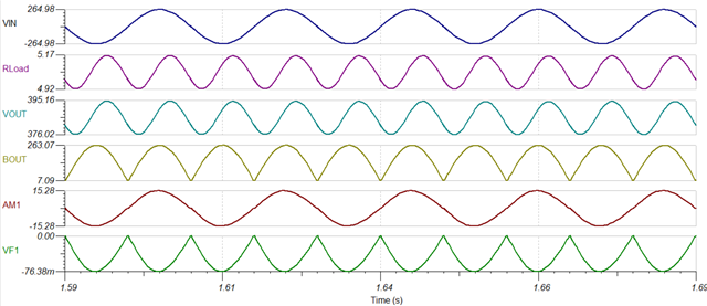
When we simulate in Webench with UCC28180 transient model, with -150mV apply in pin 3 (to pin 1), the line current begin to be distored at the pic of the line current sinusoid. it's the beginning of the action of the SOC limitation of the UCC28180D. The problem is that it acts at a lower level than the minimum value specified in the datasheet. It begins to act at near -150mV whereas the minimum value of SOC limitation should be -0,259V.

We visualize the same defect on a cabled printed circuit board with component values.

How do you explain that?

  • Hi Emmanuel,

    Thank you for the query on UCC28180.

    During SOC limit (259mV),  the input current is limited and it acts by pulling down on the VCOMP value. This has the effect of lowering the output voltage. This happens almost instantaneously : as soon as the limit is reached, the input current is limited and you will see that the output voltage begins to drop.First can you please check if you are observing this in simulation and software to confirm if SOC is triggered. Next, can you please confirm if correct choice of sense resistor was used based on design calculator and also power levels/post schematics/TINA file for which this is designed so that we can check the issue from our end.

    Regards,

    Harish

  • Bonjour,

    j'ai bien compris le fonctionnement de la fonction SOC et je vois effectivement que si je surcharge le PFC, la tension PFC chute. Les composants ont été dimentionnés L'objet de ma requête est que le seuil constaté d'action de la fonction SOC semble bien inférieur à celui spécifié dans la datasheet: environ -0,150V au lieu de -0,259V qui est en plus la valeur minimale d'action donnée dans la datasheet.

    Vous trouverez ci-joint le logiciel Webench utilisé pour faire la simulation. je vous joins également en pdf le relevé des signaux de la simulation qui montre que lorsque le signal atteind environ -150mV sur la patte 3 de l'UC28180, le signal de courant secteur commence à se déformer sur les crêtes. slum529_UCC28180 - Tina_2023-03-09.TSCTINA Diagram_UCC28180 transient response_2023-03-09.pdfWenbench design center_UCC28180 transient response simulation_Tina_2023-03-09.pdf

    Comment se fait-il que le signal de courant secteur se déforme sur les crêtes suite à l'action de la fonction SOC alors que le seuil d'action théorique ne semble pas atteint en simulation: le signal "VF1" est à environ -0,150V quand on commence à voir apparaitre une distorsion sur le signal "AM1" du courant secteur.

    Je vous ai joins le fichier Tina comme cela vous pourrez constater cela vous-même.

    Merci de me dire pour quelle raison le seuil constaté d'action de la fonction SOC est inférieur à sa spécification.

    cordialement.

  • Hi Emmanuel,

    Thank you for the reply.

    Can you please post in English going ahead.

    I see a number of problems in your circuit which is the reason for the spike at the peak of current waveform. The SOC functions works properly. I have resimulated based on your specifications ans seems to converge properly. Please see waveform below.

    I have attached the TINA file and excel document for you to review. Hope this helps.

    7080.sluc506c.xls

    slum529.tsc

    Regards,

    Harish

  • Thank you very much. it resolved my issue.