


Dear TI,
I am quite new to charging/discharging system design and I wonder if you could help me with idea initialization.
A few considerations before my questions:
The harvesting circuit requires start-up voltage of 2.6V and after that it can accept any voltage down to 150mV.
The harvesting circuit has built-in overcharging cutoff voltage of 4.2V and under-threshold cut-off voltage 3.7V (for li-po battery)
I would like to build/look for a closed-loop charging/discharging system that can handle both charging and discharging path with the following characteristics:
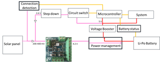
Power management circuit
1. Allows for the harvesting circuit to only charge (purple) the li-po battery when microcontroller and system are down.
2. Allows for the battery to discharge (red) to power the microcontroller and the system. This happens only when solar panel is not connected
3. Preferably has built-in battery status that can be monitored (yellow) by the microcontroller
Connection detection circuit
1. This circuit allows the microcontroller to detect (yellow) the solar panel connection with voltage above certain threshold (minimum 150mV)
Circuit switch
1. After the connection detection successful from solar panel, microcontroller allows the Li-po battery to step-down and "prime" (purple) the harvesting circuit with 2.6 V. After the first few mili seconds, the switch can disconnect, the harvesting circuit now only needs minimum 150mV to charge the battery.
2. The Microcontroller and system go into low-power mode, the harvesting circuit begins charging (purple) the Li-po battery. The microcontroller still monitors (yellow) the connection of solar panel and the battery level of the Li-po battery.
Thank you very much for your time reading this post. Any suggestions are welcomed. I am very new to this so I appreciate helps and directions.
Long story short, I need to draw power from the battery when solar panel is not connected and when battery level is above 3.8V. When the solar panel is connected, the system must "prime" the harvesting circuit at 2.6V before it starts, after which the system goes low-power and the charging process can begin.
Khoi Ly
