Hello TI experts, I'm trying to configure TPS6594 and found that I could self define some states in PFSM. I'm wondering what's the maximum number of states I can add in PFSM? Thank you.
This thread has been locked.
If you have a related question, please click the "Ask a related question" button in the top right corner. The newly created question will be automatically linked to this question.
Hello TI experts, I'm trying to configure TPS6594 and found that I could self define some states in PFSM. I'm wondering what's the maximum number of states I can add in PFSM? Thank you.
Hello Charlotte,
The limitation will come from the total memory needed for the PFSM not the number of states. That includes the complexity of the state transitions and numbers of triggers. For example a 5 state PFSM with very complex state transitions and triggers may use more memory than 8 states with very simple triggers and transitions. The GUI will prevent you from programming a device that a PFSM that won't fit.
Hi Michael, thank you for letting me know that. This is really a powerful device with a great GUI. I really like it. BTW, may I know the memory size of this PFSM?
Howdy.
Michael is currently out of office. He will be back tomorrow to review your inquiries.
best,
David Martinez
Thank you Michael. I'm trying to use code to configure my PFSM but I find it a little bit hard to interpret the codes. Can you please help me with the following questions?
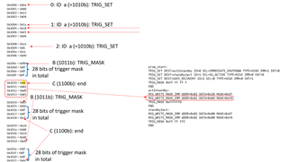
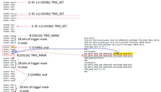
1. How should I interpret the codes in the red block? Should I read it every 4 bits? I see the assembly program tells me that this is a "REG_WRITE_MASK_IMM" command but that means I should see 2 (0010b) in the code? But instead, I see "d" after "c"(end command). How should I correlate "REG_WRITE_MASK_IMM" command to the binary code on the left?
2. How should I correlate "REG_WRITE_MASK_IMM ADDR=0x82 DATA=0x10 MASK=0xEF" to the code on the left? I could see the address 82 in 0x3011=0x82, but I could not see where "DATA=0x10 MASK=0xEF" goes in the code.
I know it might be easier to directly use GUI for configuration but coding is more applicable in our application. Can you please help us understand it?
Thank you,
Charlotte
Hello,
Please be advised that the compiler is optimizing the instructions. For example if you only change 1 bit then the REG_WRITE_BIT_PAGE0_IMM, "d", would be used in place of the REG_WRITE_MASK_IMM.
Regards,
Chris
Hi Chris,
I see. How should I correlate "REG_WRITE_MASK_IMM ADDR=0x82 DATA=0x10 MASK=0xEF" to the code on the left? I could see the address 82 in 0x3011=0x82, but I could not see where "DATA=0x10 MASK=0xEF" goes in the code. Is there also some compiler to translate 0x3012 = 0xd9 into "DATA=0x10 MASK=0xEF"? The code length somehow does not match the script length. How should do the configuration using the binary code then? Thank you.
Hello Charlotte,
REG_WRITE_MASK_IMM ADDR=0x82 DATA=0x10 MASK=0xEF is optimized to REG_WRITE_BIT_PAGE0_IMM ADDR=0x82 BIT=4 DATA=0x1. 'Dh' '82h' '100b' '1b'. You can think of data and mask being converted to bit (100b) and data (1b).
If you want to see the REG_WRITE_MASK_IMM command change the MASK to 0xEE so that more than one bit is changed.
Regards,
Chris
Hi Chris, thank you for your quick response! That's a smart way to save bits... I might need to do some calculation on my side.. If I do not do this optimization in my code, would it also work? Or my code has to do this optimization? BTW, where does this addr 0x82 go? I do not see the address 0x82 register on the datasheet is relavent to this command.
Hello,
If I do not do this optimization in my code, would it also work?
Yes. The optimization is not required.
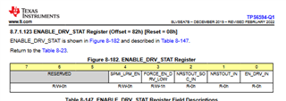
BTW, where does this addr 0x82 go? I do not see the address 0x82 register on the datasheet is relavent to this command.
https://www.ti.com/lit/ds/symlink/tps6594-q1.pdf#page=291
Regards,
Chris
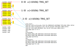
Hi Chris, thank you for letting me know that. It's good to know that I do not have to do the optimization. May I know how should I interpret the trig_set parts? I can understand that this part begins with triger set (a:1010b) and trigger ID (0,1,2). What does the code after that mean?
The assembly code is telling the PMIC which PFSM sequence to execute based on the trigger event. For example if the IMMEDIATE_SHUTDOWN trigger is HIGH, it will execute the "act2standby" PFSM sequence.