This thread has been locked.

If you have a related question, please click the "Ask a related question" button in the top right corner. The newly created question will be automatically linked to this question.

TPS23523: Questions on How to Use

Part Number: TPS23523

Hello,

I'd like to ask some questions about how to use TPS23523.

Questions

  • I guess that the insertion delay time tID defined as 32 ms (Typ) in the data sheet will be used to delay a restart of TPS23523 after an OFF state caused by an over-current event, but can I change the delay time?
  • What was the background that defined the tID as 32 ms (Typ) in the first place? I suspect that there were some requests of shorter of longer delay time than 32 ms when defining the TPS23523 back then.
  • How can I set input voltage thresholds for a device start-up and a device turn-off?
    • Start-up: The TPS23523 starts up when the input voltage of nominal -48 V goes below -36 V.
    • Turn-off: The TPS23523 turns off when the input voltage of nominal -48 V goes above -32.5 V.
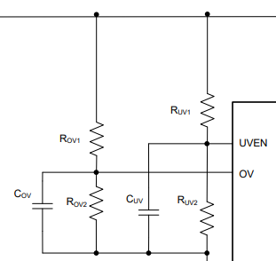
  • Figure 14 in the section 9.2 Typical Application shows two capacitors — COV and CUV — are put in parallel with the resistor dividers that set OV and UVEN thresholds, but what kind of effect will they bring to the system? In other words, what are the role of these capacitors in the application?

Best regards,
Shinichi Yokota

  • Hi Shinichi,

    Thanks for reaching out to us. This 32 ms delay can't be changed. The purpose of insertion delay is as follows.

    Insertion Delay State In this state the hot swap FET is turned off and the controller is waiting for the insertion delay to finish. This allows the input supply to settle after a Hot Plug. If any of the following occur, the controller will be kicked back to the OFF state:

    • Input voltage is not in the valid range.

    • VCC is below its UVLO threshold and the IC doesn’t have enough power to operate properly.

    Once the insertion delay is finished, the controller will move to the Start-up state.

    The device incorporates a fixed delay block of 32 ms, which is being used for insertion delay, deglitch delay of PGb, and restart delay after the 64 times timer discharge & charge cycles. 

    Please place an appropriate resistor divider  network on the UVEN pin from RTN to VEE to select proper under voltage lockout threshold as per the system's requirement.

    Filtering capacitors, CUV and COV are be added to the UV and OV to improve immunity to noise and transients on the input bus. These should be tuned based on system requirements and input inductance.

  • Avishek,

    The device incorporates a fixed delay block of 32 ms, which is being used for insertion delay, deglitch delay of PGb, and restart delay after the 64 times timer discharge & charge cycles.

    How can I insert a delay of more than 32 ms before the hot swap FET is turned on after the board is plugged in? About 200 ms, for example.

    Best regards,
    Shinichi Yokota

  • As we are discussing through email, I am closing this thread. 

    Please click on "This resolved my issue".