This thread has been locked.

If you have a related question, please click the "Ask a related question" button in the top right corner. The newly created question will be automatically linked to this question.

UCC3895: cycle-by-cycle current limiting

Part Number: UCC3895
Other Parts Discussed in Thread: UCC2895

Hello,

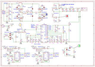
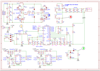
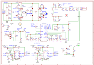
I am designing a CMC PSFB converter based on UCC3895. I ran into a problem with cycle-by-cycle current limiting.

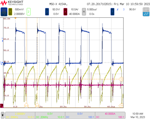
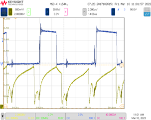
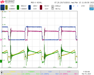
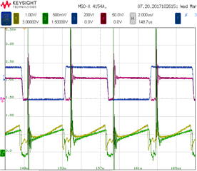
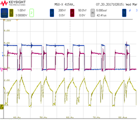
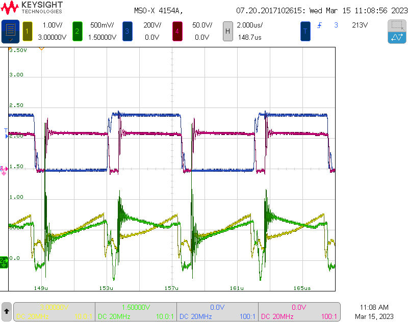
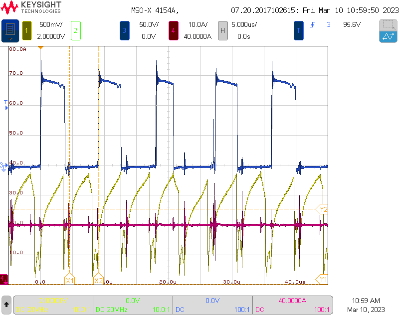
When the voltage at the CS pin reaches the 2V threshold, the duty cycle starts to change rapidly and asymmetrically. This causes audible noise and could even lead to primary TX saturation (in this case 2.5V threshold kicks in, restarting the IC).

I expect that the duty cycle should change smoothly and symmetrically, reducing the output voltage when the load resistance decreases, thus limiting the output current. But that occurs only when the load resistance is too low, when duty cycle is already around 55% and less. From ~55% down to ~0% duty cycle changes smoothly and symmetrically. From ~80% down to ~55% duty cycle changes rapidly and asymmetrically.

  • Hello,

    I am reviewing your inquiry and will get back to you shortly.

    Regards,

  • Hello,

    It sounds like your current sense resistor is sized to large.  You should only hit the cycle by cycle current limit of 2 V when the converter is entering an over current condition.  Consider resizing the current sense resistor.

    Regards,

  • Hello Mike! Thank you for your quick response!


    I understand that the voltage on the CS pin should reach 2V only at the moment  when the converter is entering an over current condition, and the moment of tripping is correct. This is not the question. My question is why my current protection does not work normally after tripping. 

    You see, I expect that when the cycle by cycle current limit trips, the duty cycle should decrease evenly limiting the output current, but in my case converter loses stability and the duty cycle fluctuates from almost completely open to almost completely closed. All this is accompanied by noise and crackling. The protection clearly should not work like that. Please can you advise what could be the reason.

    Yellow signal - voltage at the summing point. Blue signal - output diode voltage. Red signal - output current. Converter runs, current protection is tripping. Audible noise appears, you can see duty cycle variations on a blue waveform.

    Here is schematic

  • Hello,

    I reviewed your schematic and TI does not recommend using the current sense transformer (CT) in series with the H Bridge.  The DC information could be loss and it could cause problems.  It is recommend that you put the CT in front of the H Bridge.  The proper placement of the CT is shown in the data sheet applications section of the UCC2895.

    In regards to your current sense signal.  It does not look correct and there is evidence of transformer saturation.  The issue may be due to the CT placement and/or your output inductor could be saturating.

    I would suggest moving the CT and reevaluating.

    Regards,

  • I added a current transformer before the H bridge in the circuit as you recommended (please note TCS2.1, TCS2.2 below).

    Unfortunately, the signal from this sensor is asymmetrical. Please look at the waveforms below.

    The only way to fix this situation is to short the resonant choke L1 (oscillogram below, L1 shorted).

    On the current sensor in series with the H-bridge (Yellow signal), the signal has a normal shape regardless of the presence of the choke L1. With this current sensor the voltage feedback loop functions stably (the output voltage is stabilized over the entire load range). The problem I described in the first post exists as soon as the current protection threshold is triggered. Before this event everything works fine. I noticed that the duty cycle QD is less than 50% when the protection is triggered, is this OK?

  • Hello,

    The waveforms should not be asymmetrical.  What are the yellow and green waveforms? 

    Did you add slope compensation to your design?  You also might be running into subharmonic oscillation.  I would also make sure that you added half the inductor ripple current down slope to the current sense signal.  

    Regards,

  • Please note the schematic from the previous message. On it the signal measurement points are signed with colored numbers.
    1 - yellow - signal at summation point (added slope >1/2 of inductor ripple current down slope, and current signal is taken from the sensor connected in series with the H bridge). This sum is now fed to the RAMP and CS pin of the chip. The output voltage stabilization works well with this signal.
    2 - the green signal is the signal obtained at the output of the unipolar transformer TCS2.1, TCS2.2 (without adding compensation). This signal is asymmetrical for some reason. Diodes D9, D10 are fine. I replaced IDW30G65C5 with IXYS DSEI30-10A, the picture has not changed. Only shorting the choke L1 helps, but obviously this is not the solution.
    3 - blue signal is the voltage at the drain of the QD transistor (see the schematic).
    4 - red signal - voltage at the cathode of the rectifier output diode.

  • Hello,

    I am reviewing the thread and will get back to you soon.

    Regards,

  • Hello,

    I reviewed the circuit when you the CT to the input of the HBridge.  Did you remove the other CT in series with the transformer and connected to D2?

    The schematic looks like you using both CTs.  If this is the case they might be fighting each other.

    Regards,

  • Hello!

    The CTs cannot fight because TCS 2.2 is not connected to the rest of the circuit. The green waveform (point 2) is obtained at R21. R21 is now only connected to the oscilloscope. I don't think the converter can work at all using the green waveform on the RAMP pin, so only the signal from TCS1.2 (yellow signal) comes to this pin. The voltage stabilization by the way works with this (yellow) signal.

  • Hello,

    Did you short out the CT in series with the transformer and use signal 2 to control your circuit?

    You should had a reset resistor across D14 and D8 for the CT to ensure it resets.

    1 k should be enough.

    Regards,

  • The main reason for such oscillatory behaviour was lack of slope compensation. The reason I didn't notice this from the beginning is that when the load current was low, the compensation ramp was sufficient, and when the load current was increased (and of course voltage on CT also increased), the compensation ramp just drowned in the ramp from the current sensor. From what I understand this effect was caused by the relatively high output impedance of Q5 (BC337-40) due to the high value of R26(16k). Changing the R26 resistor to a lower resistance resistor <1k completely solved the oscillation problem.
    The second problem with unipolar CT (TCS2.1) (asymmetric green waveform) was caused by misconnection of the cathode pin of D9. It was connected to the + of C1 directly in other words it was connected before the current sensor. As soon as I connected it according to the schematic the appropriate waveform was obtained.

  • Hello,

    Thankyou for letting us know how your progress was going.

    Regards,